跳到内容
跳到内容 
What Is Hardness?
Material hardness refers to the resistance of a material’s surface to localized surface deformation or its ability to resist a pointed tool’s penetration. This property is critical when determining a suitable metal in applications with two metals impacting each other- the one with high rigidity will cause plastic deformation or scratch the less hard one.
The strength, strain, viscosity, toughness, plasticity, viscoelasticity, and ductility determine the hardness of a material. How hard a material is is an essential factor when considering a part’s wear resistance. Besides, harder materials are famous for their extremely high resistance to wear.
Machining engineers accomplish hardness testing by pressing a probe with a hard tip onto a material at a particular force and calculating the depth of plastic deformation or amount of indentation the probe makes. Hardness testers are also used to measure the impression size produced by the indenter/probe.
Metals such as steel exhibit roughly proportional hardness and tensile strength. Diamond is a typical material with high hardness and is commonly used for CNC machining tools. The harder a material is, the more difficult it is to scratch or dent.
Measuring the Hardness of a Material

Hardness is one of the commonly documented material properties and a standard one-off measure of material quality used by design engineers. We will discuss the different tests and scales professionals use to measure and quantify the hardness of material below:
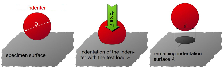
Most hardness tests adhere to similar standardized procedures, which involve pushing an indenter of a specific shape and material into the test material’s surface with a predetermined force. Then, the indentation’s dimensions are documented. These values are used to measure the hardness.
The Brinell, Rockwell, and Vickers tests are typical tests professionals commonly use.
- Brinell Hardness Test: The Brinell test uses a 10 mm diameter steel ball with a standard force of 29.42 kN.
- Rockwell Hardness Test: This test is extremely diverse, with different indenters, loads and scales. It applies a unique two-step load – a minor load and a major load.
- Vickers Hardness Test: It tests the material’s hardness with a pyramid-shaped diamond indenter. It uses light indentation loads and applies mainly to thin sections and smaller components.
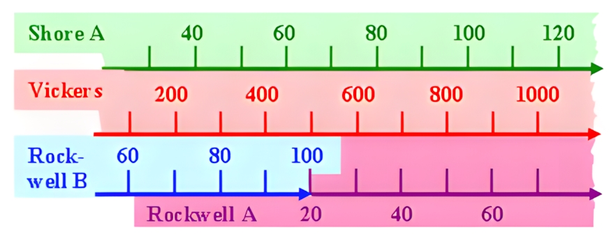
Hardness scales vary according to the different hardness tests. Each test is optimal for specific applications. For instance, the three tests discussed earlier in this section apply primarily to metals. Conversely, the shore hardness scale is extensively used for elastomers and other polymers. Engineers sometimes need to change readings from one scale to another. A good practice is to consult conversion charts such as the one below:
What Is Stiffness?
Material stiffness indicates a material’s tendency to return to its original state after exposure to force. This material property is crucial to engineering design and manufacturing. Materials with lower stiffness deform more than those with high stiffness.
A material’s stiffness and elastic modulus are connected: stiffness increases as the elastic modulus rises. The modulus of elasticity refers to the value of a material’s stiffness on the elastic region only. Since a material’s elastic modulus relates to its stiffness and strength, check a material reference handbook to identify its elastic modulus and determine its specific strength or stiffness.
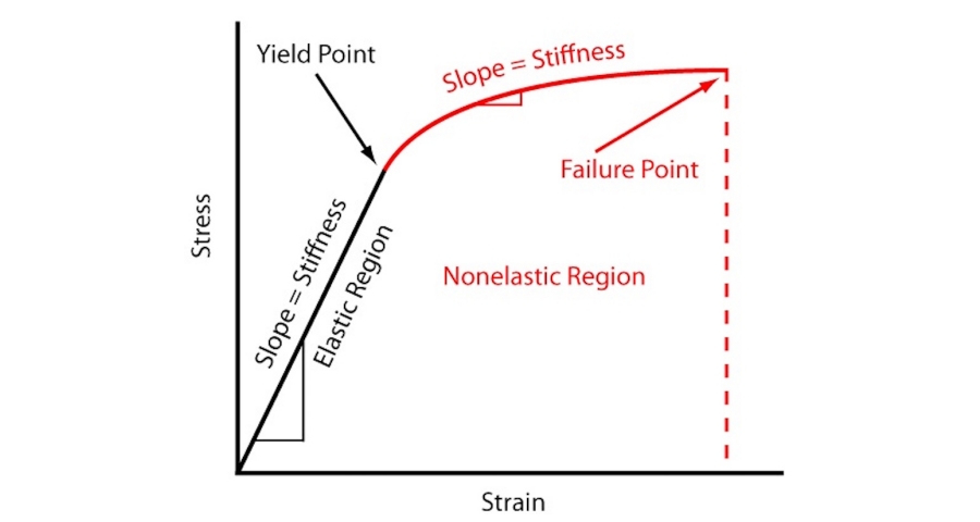
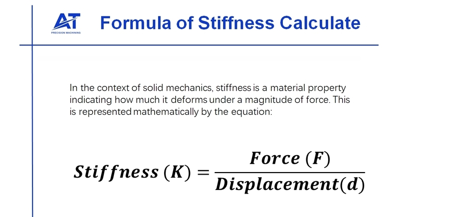
The stress-strain curve quantifies a material’s stiffness, as illustrated above. It indicates the ratio between changes in stress and strain. Generally, a material’s stiffness is calculated with the formula:
Depending on the intended application, stiffness is of various types, including beam stiffness, torsional stiffness, axial force ratio, tension/compression stiffness, shear stiffness, bending stiffness, spring stiffness, and axial linear strain (EA). Hooke’s Law provides a better understanding of the stiffness concept. It describes stiffness as the ratio between the force a spring is exposed to versus its extension as a reaction to the applied force.
Stiffness in Machining
We’ll discuss a real-life example of stiffness in the world of machining. The cutting tool must be stiff enough to resist deformation and handle the cutting force produced by the cutting process. While small deflections are regular, excessive deformations can break the cutter or deteriorate a part’s tolerance.
Hence, machining experts often apply their knowledge before choosing CNC tools to determine whether the cutting tool’s deflection will fall within acceptable limits. Below is a simplified calculation of the process below:
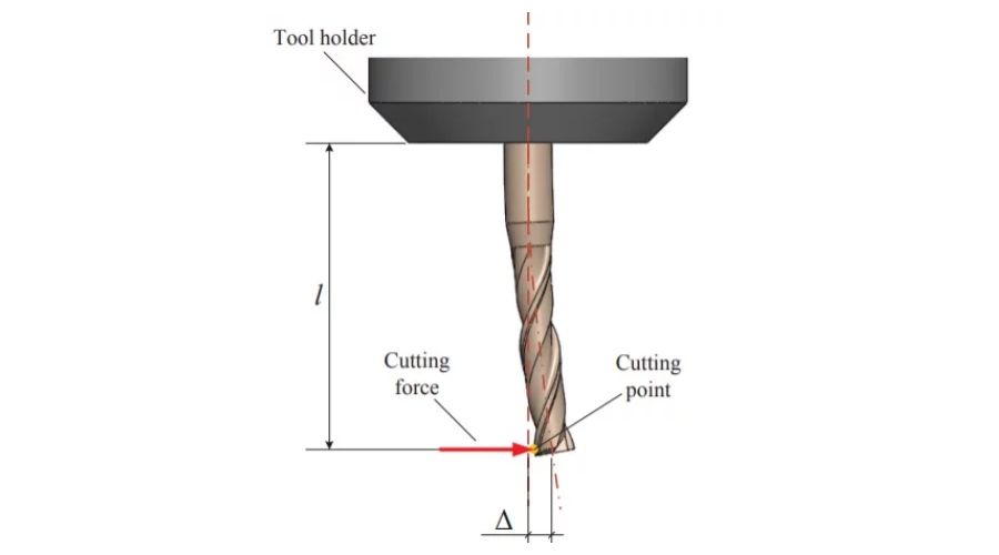
The CNC tool functions as a cantilever beam in a machining setup. A point load at the tool’s tip is presumed to be the cutting force. However, the tool’s stiffness (cantilever beam with a point load) is measured by:

The ‘E’ in this equation is the tool material’s modulus of elasticity, ‘l’ represents its moment of inertia, while ‘L’ is the length of the stool sticking out of the spindle. However, we can calculate the expected tool deflection using the cutting force since we understand how force, surface deformation, and stiffness are connected.

What Is Strength?

The strength of a material represents how much stress it can handle before permanent deformation or fractures. Tensile strength and hardness indicate a material’s resistance to plastic deformation. Material strength is one of the foremost properties engineers consider when choosing materials for their design. Besides, strong materials are less likely to deform easily.
Various strength types, including yield and ultimate tensile strength, are worth considering based on the intended application. A material’s yield strength refers to the maximum stress it can handle before breaking or failing. Conversely, ultimate tensile strength is the highest stress a material can handle before it breaks or fails.
Compressive Strength
Stress applies to machined parts differently, even though most materials react similarly under other stress. Compressive strength represents the material’s strength when exposed to compressive forces. The response is the same: the material deforms (begins plastically and plastically later) under compressive loads. Finally, the material breaks apart at a particular stress value.
Usually, tensile strength is lower than compressive strength since compressing materials is more challenging than elongating them. Hence, it is a critical feature in engineering design if the part experiences compressive forces. Typical applications where compressive strength is essential include automotive suspension systems, hydraulic presses, and columns.

With 30 years of CNC experience, Sam is dedicated to solving complex design and machining challenges, ensuring precision and efficiency for every customer project.
[email protected]Best Practice for Hardness, Stiffness & Strength
Maintain constant feed rates in 304/316 Stainless; never dwell or rub. These metals harden instantly under heat and pressure, creating a hard "skin" that destroys cutters.
Contact Our CNC Machining ExpertFracture Strength
As the name implies, fracture strength refers to the stress value when a material fails entirely and begins to break apart (fractures). As an extreme stress point, avoiding it during the design stages is important. Tool breakage would be an apt example in the world of machining. A cutting tool becomes useless when its cutting edge wears off due to overstressing.
Yield Strength
A material’s yield strength is its strength before its yielding point. They represent a point on the stress-strain curve prior to the elastic material deformation. It regains its original form if the stress is removed. However, permanent plastic deformation occurs when the material is stressed beyond the yield point and doesn’t regain its original shape even if the load is removed. The yield strength is arguably the most critical property for design engineers since plastic deformation is unsuitable for most components.
Ultimate Tensile Strength
A material’s ultimate tensile strength refers to the maximum tensile stress it can attain. Besides, it is another critical point on the stress-strain curve. Also, ultimate strength indicates the point after which the material moves towards failure, which occurs in the plastic deformation zone. From a design perspective, measuring if the part is expected to experience plastic deformation is typically essential. The stress should remain below the ultimate tensile strength to restrain extreme deformations and fractures.

Tracy is a sales manager with 18 years of experience in CNC machining, specializing in precision components and client solutions.
[email protected]Best Practice for Hardness, Stiffness & Strength
Minimize tool overhang aggressively. Stiffness decreases by the cube of length L3. A 2x longer tool is 8x less rigid, causing immediate chatter in hard metals like Titanium.
Contact Our CNC Machining ExpertWhat Is Young’s Modulus?
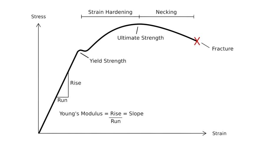
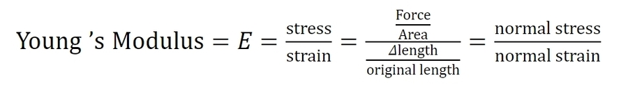
Young’s Modulus stress-strain curve is an apt reference tool that helps to understand better the relationship between a material’s strength and stiffness. Young’s Modulus, also called elastic, shear, or bulk modulus. Also, it is the ratio of normal stress to normal strain and represents a material’s ability to resist elastic deformation under loading conditions. In basic terms, it describes the ease at which a material stretches and deforms.
Young’s modulus remains constant for any particular metal and is not influenced by external stressors, including heat treatment or cold work, while strength varies from one grade to another.
Understanding Stress and Strain in Materials
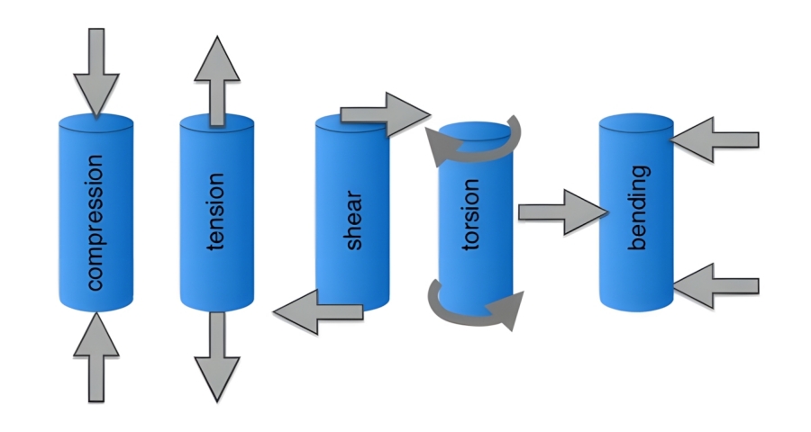
Stress is an internal force caused by an applied force acting on a cross-section of a particular mechanical or structural component. On the other hand, strain refers to the change in a component’s shape or body size (deformation) resulting from an applied force. Strain is of two types, which correspond with the two variants of stress:
- Shear Stress: It occurs due to shear strain; deformations occur parallel to the cross-section.
- Normal Stress: Deformation occurring perpendicular to the cross-section and caused by normal stress.
How to Retrieve the Mechanical Property Data of a Material
To retrieve a material’s mechanical (or electrical or thermal) property data, consult the manufacturer’s website or the American Society for Testing Materials (ASTM). The available data values often range from material mechanical strength and stiffness to hardness and tensile strength. Matweb is a reliable resource with accurate and searchable data on materials that can be obtained quickly. However, if you are unfamiliar with reading material data sheets to get mechanical property data, our experts will gladly assist you!
Hardness vs Stiffness Vs Strength: Their Comparison
Hardness, stiffness, and strength are predominant variables that determine a material’s suitability for an engineering application. Since these properties play a pivotal role in deciding a metal’s performance, it doesn’t mean other material properties are unnecessary. Moreover, these three properties have a particular relationship amongst themselves.
Tensile strength and hardness are typically proven to be directly connected. In general, high strength translates to high hardness. The same goes for stiffness and strength since strong materials mostly exhibit high stiffness. Hence, it is crucial to choose stronger materials when you need components that exhibit low deformation.
However, the case is different with glass. It is a brittle material, stiff but not strong. Hence, they do not deform much under load but enter the plastic deformation zone and break quickly. As a result, evaluating these material properties individually would be best to attain optimal outcomes. Often, the discussed underlying relations can be directly inferred/presumed. By doing so, design engineers should be meticulous and always confirm the correctness of their assumptions for materials intended for their engineering applications.
Helpful Practices for Designing Hardness, Stiffness and Strength
Engineering design is often demanding, requiring outstanding creativity, skill, and expertise. To design engineering components successfully, here are the best practices to keep in mind:
Determine Critical Components
Identifying the critical components of your design is an essential consideration in the early stages of your product design and development, such as when generating the CAD model. You must identify critical components that will handle impact, such as constant, concentrated, uniform loads, etc. It helps to determine the required strength or stiffness for the components. Similarly, experts recommend using block-diagram modeling or bond graphs to construct a graphical representation of complex dynamical systems and use software to model advanced systems.
Calculate Stress and Determine the Applied Forces to Each Component
Engineering experts often calculate the expected stresses on mechanical components to identify where forces are substantial or where complications may arise. You can use instrumentation methods and data analysis to determine your model’s reaction to various inputs. Evaluate fatigue and creep variables in subsystems and those related to the working environment of the mechanical components. However, AT Machining professionals recommend consulting the mechanical engineering book design for a refresher on determining the stress that designed components are exposed to.

Material Selection
Each material possesses its distinct electrical, thermal, and mechanical properties. Different materials are suitable for various purposes. Ceramics, for instance, are brittle materials that hardly deform before fracturing. Hence, cracks may occur rapidly with minor plastic deformation. Meanwhile, metals have two modes in reaction to an applied stress: brittleness or ductility. While brittle materials are not accompanied by plastic deformation before fracture, ductile materials experience plastic deformation before fracture.
While polymers’ ductility and brittleness may depend on temperature, fracture in ductile metals occurs in different stages. It would be best to determine the manufacturing processes that offer the desired material properties for your raw materials. In addition, consulting engineering handbooks for reliable material data when testing materials is necessary to ensure conformity with ASTM standards.
Furthermore, you should pick materials based on the environmental conditions to which the mechanical components will be subjected. A material’s chemical composition determines its ability to resist environmental conditions like chemical corrosion, salt solutions, or water. Stainless steel, titanium, and aluminum are suitable materials for applications requiring components with good resistance to environmental conditions.
However, understand that the hardness of a material determines its ability to resist abrasive environments like desert conditions. A general rule of thumb is to choose a material with higher hardness than the abrasive material to which it is exposed to avoid material loss.
Verify Designs Before Prototyping
Optimize and verify your design before prototyping, and use CAD software to examine and optimize your design’s geometry. FEA analysis and numerical analysis are suitable options, and when compatible, cross-check your analysis with hand calculations before prototyping for cost and time efficiency.
More so, design for manufacturing (DFM) can help optimize your design before prototyping. Even the most brilliant designs can fail if you don’t check for the limitations of the manufacturing methods. However, worry less for AT Machining, which provides reliable instant DFM feedback for any design you upload onto our platform.
Conclusion
Strength, stiffness, and hardness are core material properties in the realm of metal fabrication. Each of these properties, although synonymous, influences a metal’s performance in different ways. Understanding how a material reacts under various load conditions helps guide your choice of the suitable material for your application.

AT-Machining’s professionals have extensive experience working with different machining materials, including titanium, aluminum, stainless steel, and other commonly used materials. They understand the differences between their hardness, stiffness, strength, and other mechanical properties. Hence, trust us to deliver metal products that meet stringent industry standards and design requirements. Contact us today; we offer instant DFM analysis and quotes.