跳到内容
跳到内容 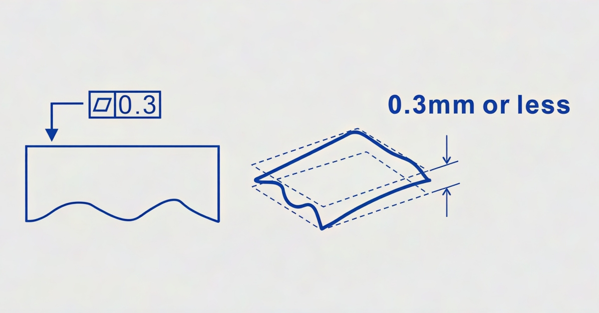
What Does Flatness Mean in GD&T?
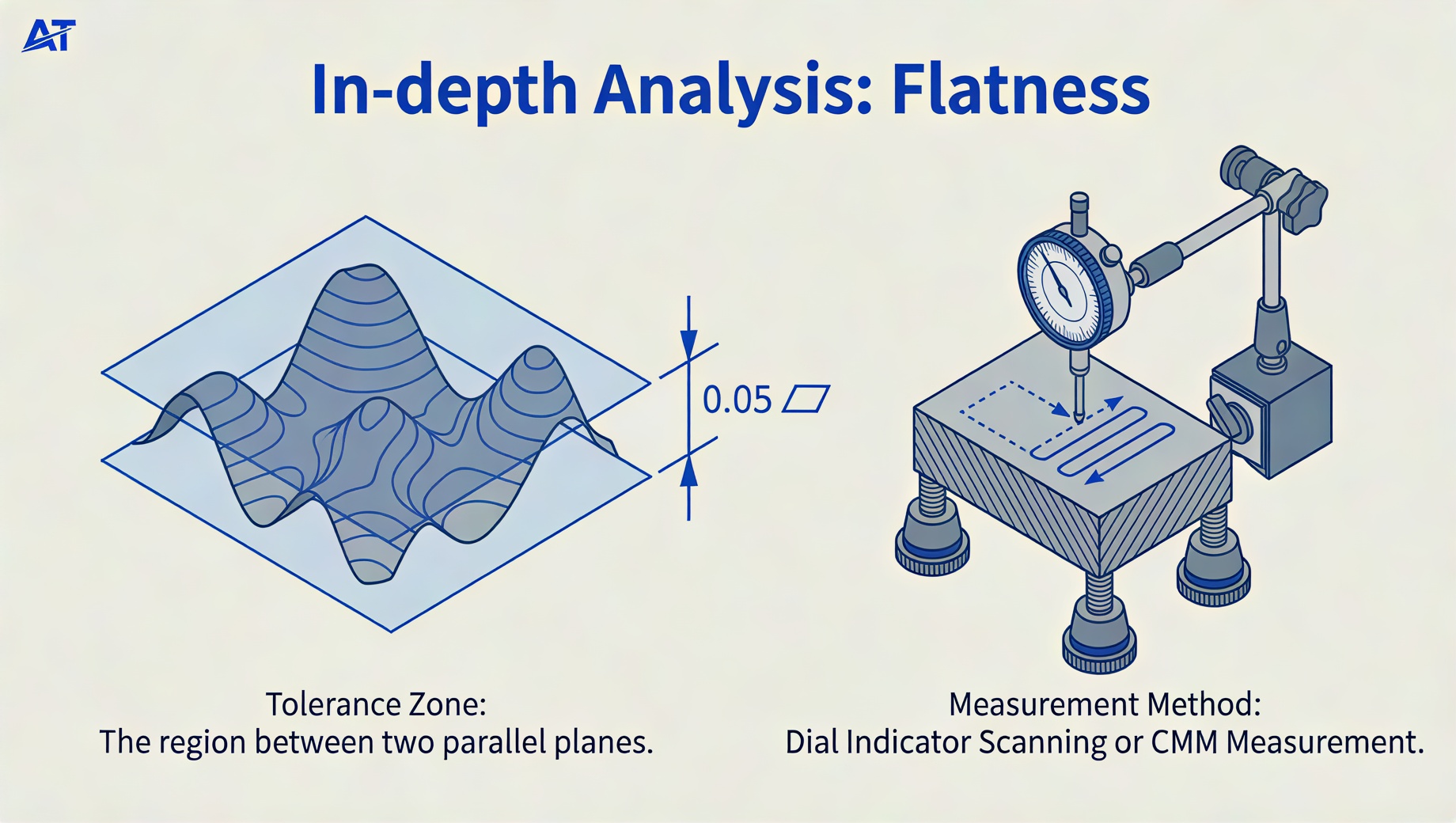
In geometric dimensioning and tolerancing, flatness controls the permissible deviation of a part’s surface from a perfectly flat plane. The tolerance zone is marked out by two sets of parallel planes within which the entire referenced surface must lie. Thus, it restrains surface variation or waviness without tightening any other dimensional tolerance on the surface.
Generally, no surface is perfectly flat, despite the common use of parts with a flat surface in most applications. Flatness tolerance applies to any surface whose flatness must stay within specific bounds for the part to function properly. It controls the form of a surface in cases where flatness is a critical design requirement.
More so, design experts rely on GD&T to develop parts with a surface flat enough for the intended application. More importantly, flatness refines the size tolerance of stacked features for better assembly of mating components.
How to Specify Flatness Symbol and Callout on a Drawing
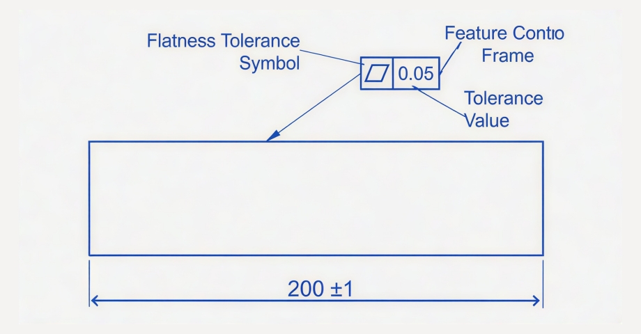
Product designers specify tolerance details on a part with a specific flatness callout. We will discuss the feature control frame (FCF) for the flatness GD&T symbol in this section.
The flatness feature control frame is straightforward. The image above contains a typical flatness callout that indicates the flatness symbol’s position and tolerance value in the feature control. Since a datum is not a requirement, the callout only includes the geometric characteristic symbol (represented by a parallelogram) and tolerance value.
Flatness Tolerance Zone
Flatness GD&T features a 3D tolerance zone marked by two parallel surfaces below and above the referenced surface. The entire surface must sit within these two virtual planes to meet the specified quality requirement.
The distance between the two planes outlines the surface flatness tolerance’s ‘tightness’. Depending on design intent, the designer specifies a tolerance value based on the required level of precision, which defines the permissible variation a surface has from its true form.
As stated earlier, the flatness symbol doesn’t reference a datum because it does not control the referenced feature against any standard datum feature. As such, it provides an independent form of tolerance on the surface, irrespective of its orientation or position relative to other features in the part.
The above image illustrates a flatness callout on the top surface of the part. However, the crucial point is how flat the top surface remains within a 0.1-thick tolerance zone. It does not matter if it is tilted with regard to the part’s bottom surface.
Applying Flatness in GD&T
Flatness is a core GD&T concept with different ways to apply it to any area of surface or feature. It is an easy GD&T tool for designing parts with varying quality requirements and geometries. Let’s explore the different ways to apply flatness in GD&T below:
Flatness on a Surface

It is the most common way to apply the flatness symbol. As stated earlier, the surface flatness tolerance zone consists of two parallel planes (below and above the surface). Here, the flatness callout sits on an extension line or points directly at a flat surface from the referenced surface.
For the flatness symbol to be applicable, the placement of the flat surface doesn’t have any restrictions. More so, the referenced surface may be discontinuous, inclined, or even inside a slot.
Flatness on a Derived Median Plane (DMP)
Instead of a surface, design engineers apply the flatness symbol to a feature of size in this scenario. The control feature is the virtual derived median plane (DMP) of the referenced feature of size. Flatness on a DMP has several applications, especially in tolerance stacks or stacked components.
When you use the flatness symbol on a DMP, it is important to understand that the modifiers, such as the Least Material Condition (LMC) and Maximum Material Condition (MMC), apply to it.
The flatness callout in the illustration above contains the MMC modifier symbol (Ⓜ). In the above figure, the part’s thickness must remain within the range of 0.995 – 1.005 at all points, as it relates to the tolerance. However, the part’s overall form (bending, waviness in the DMP) might vary up to 0.01 because of the flatness callout with the MMC modifier. Hence, the actual functional tolerance zone is 0.005 + 0.01 = 0.015, and it caters to both side and form variations.
Local Flatness per Unit
This application of the flatness symbol is defined separately on the drawing in some cases when the local flatness requirements vary from the overall flatness requirements. This is often so when local flatness becomes a functional requirement, or the referenced surface is extremely big and difficult to control.
That is, sealing devices, including seal rings and gaskets, must be fully flat as a whole but must remain very flat in small local zones to guarantee effective sealing. You can define the local flatness per area or unit length on the surface. The examples above show that the surface must remain within the local tolerance margins for all possible local zones.
For example, in situations where there is 0.01 flatness tolerance per ϕ25, no local ϕ25 circular zones should be on the surface where they exceed the 0.01 tolerance.
Common Methods Used to Evaluate Flatness GD&T
Most people often ask the question: how is flatness measured? Manufactured parts are dispersed to the quality department along with their drawings. The quality control experts rely on diverse tools and methods to ensure exactness in surface measurements. Let’s dive into the major methods to measure flatness with varying effort, time, and degrees of accuracy.
Height Gauge
Measuring for flatness using a functional gauge is a standard tool for measuring flatness in GD&T and is accurate for general engineering purposes. The operator positions the part’s bottom surface on three columns of the same height. Then, adjust the heights of these columns to model a perfectly flat plane.
Then, slide the indicator of the height gauge across the surface and monitor its deviation throughout the procedure. The part passes quality if the needle deviation remains within the flatness tolerance limits.
However, it is crucial to ensure the flatness of the three-point mounting because a consequent tilt in the referenced surface would make the measurement inaccurate. Some area of the part hangs in the air since it sits on three columns. Consequently, sensitive geometries bend under gravity or due to the height gauge’s action, resulting in wrong measurements.
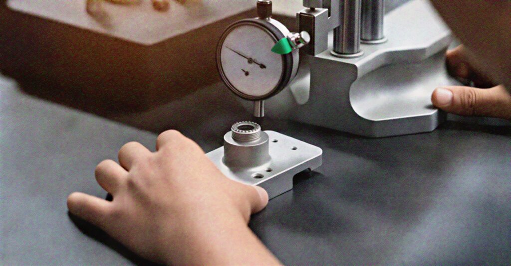
Surface Plate
This is another common way design engineers inspect flatness. The operator securely places the part on a surface plate and slides a dial gauge across the surface while monitoring the deviation. The surface plate is usually a flat granite table with good thermal stability and remarkable damping.
When using a surface plate to examine flatness, it is important to ensure the surface plate is remarkably flat and maintain a horizontal orientation to attain an accurate deviation in the flatness of the actual surface.
Coordinate Measuring Machine (CMM)
A coordinate measuring machine is one of the most accurate equipment that quality control experts rely on to inspect the surface of a part to ensure it meets flatness tolerance. Advanced CMMs are automated, independent of plane orientation, and remarkably precise. These machines work well with CAD software, thereby providing engineers with more convenience and flexibility when performing quality checks.
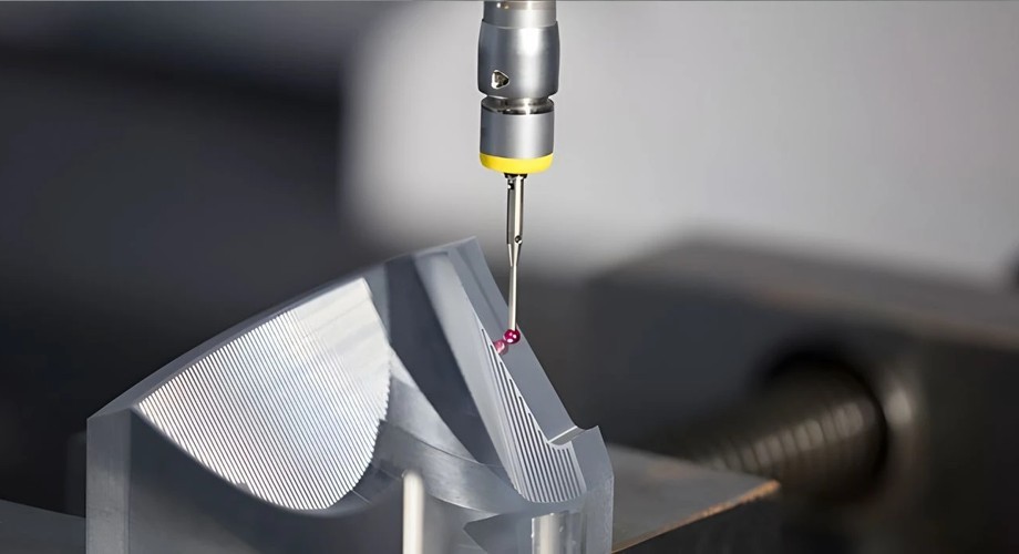
Inspecting with CMMs is a digital method often less time-consuming and provides an incredibly accurate measurement. These cutting-edge machines create virtual planes that imitate the surface being inspected. It involves sampling the surface at various points and creating a 3D point cloud. The number of measurements is based on the part’s size, dimension, and the required level of accuracy. Then, the CMM software examines the point cloud to confirm the flatness tolerance and calculate using several algorithms. The minimum zone and best-fit plane algorithms are the two standard methods.
For the minimum zone method, the algorithm positions two parallel, closest possible planes to the whole point cloud. These planes specify the tolerance zone, and the flatness of the surface is the distance between them.
In the best-fit plane scenario, the algorithm fits the best possible plane to the obtained Cartesian points and then calculates the maximum deviation of the plane from extreme points in both directions. This value represents the flatness tolerance value.
How Does Flatness vs. Straightness vs. Parallelism?
There is often a natural misconception between straightness, flatness, and parallelism symbols in GD&T since they are geometric tolerances that define the orientation and shape of features of a mechanical part. We will consider some of the key differences of these GD&T symbols in this section:
Flatness applies to the Derived Median Plane (DMP) or planar surface. It controls how much a surface is allowed to deviate from a perfectly flat plane. Flatness controls the entire surface and is not dependent on any datum. General applications of flatness include maintaining adequate contact between mating surfaces and preventing warping in thin metal parts and mechanical breakdown as a result of stress concentrations. Flatness controls apply to gasket surfaces, machine bases, mounting plates, and sealing surfaces.
Straightness controls the permissible deviation of a line element or axis from an ideal straight line. It is a form control that focuses on the axis of a cylindrical feature, shafts, or the straightness of a line on a surface. The straightness tolerance zone sits between two theoretical parallel planes and is independent of datums or any GD&T symbols. Typical uses of the straightness symbol in GD&T include linear motion components or features, axes alignment in shafts, and guide rails.
Parallelism is an orientation control that defines the orientation of a feature relative to a datum reference. Although it has a similar definition to flatness, it is defined by two parallel lines within which a surface must lie. However, parallelism requires a reference to a datum surface because the specified tolerance zone’s orientation must be parallel to a datum. Parallelism is a critical tool in maintaining alignment in assembly mating surfaces, bearing surfaces, and machine tool beds.
Key Takeaways

Flatness is a key geometrical control in GD&T, which offers engineers the tool to limit the variation in a surface form from an ideal plane. Flatness tolerance allows product design teams to communicate critical design requirements, ensuring parts are manufactured to meet the specific requirements. AT Machining is your best bet if you need on-demand custom parts that meet tighter tolerance demands.
We are a top CNC machining service provider with good years of experience and expertise to deliver parts with consistent quality. Our team of experts can leverage precision measurement techniques and advanced tools, including optical and laser systems as well as CMMs, to guarantee every part meets strict GD&T standards.Contact us today for professional assistance! Our team of expert engineers can help optimize your product design to achieve desired precision and ensure the manufacturability of parts.