跳到内容
跳到内容 
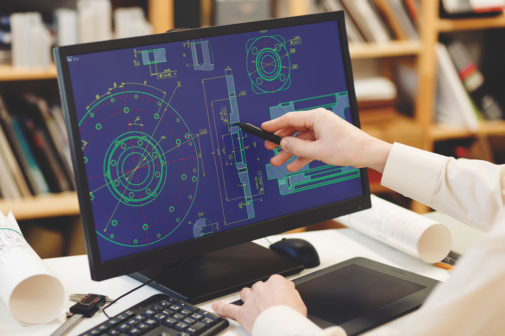
The world is fast becoming a place where everything is technologically inclined. There are several complex manufacturing projects, and manual production methods are now less effective. CAD file format for CNC machining plays a vital role in the current manufacturing trend.
This technology makes 2D or 3D designs of product parts with excellent image quality. Since CNC machining is a computer-based manufacturing process, designers and engineers need CAD software to draft files for CNC projects. Manufacturers use software programs like the CNC Mastercam to design Nc files for making mechanical parts. These NC files help collect and save scientific data and other related metadata.
There are many CAD software programs available for designers and manufacturers. This article will discuss the various CAD file formats available for CNC precision machining. We would also help you understand how to send and convert CAD files to get a CNC quote.
What File Format is Best for CNC Machining?

The CNC file takes a ‘G Code’ format that dictates the movement of the CNC machine. The G-Code is a compiled digital instructions and guidelines that govern the machine tool while in the 3D space. However, a computer-aided manufacturing program makes it easier to create 3D CNC file formats.
There are different CNC machining file formats for designing projects. However, some of these formats stand above others when it comes to manufacturing applications. They include the following:
STEP Format
The STEP format, also known as the STP format, represents the standard for product data sharing. STEP format is the best file format for 3D models exchange. This is due to its neutral file format nature, being one of the non-proprietary formats.
When you share a CAD file with a third party, remember to add any of the STEP files. This is because the majority of the CAD packages can receive and send data to this STEP file. Thus, the standard gets updated frequently. The most recent update is dated 2016.
AP203 vs. AP214 vs. AP242
When you decide to send CAD files in STEP format, you are bound to come across these three STEP types. Generally, AP242 is the best since it is the most recent version of the STEP standard. It also hosts information concerning the intended component.
You need to know that almost all CAD software can assess and open all these three versions. However, AP214 and AP242 are your best bet for special features such as color communication. AP203 lacks the color feature.
IGES Format
The IGES format is often pronounced “eye-Jess” or IGS format, abbreviated for Initial Graphics Exchange Specification. It is an aged specification with the last update in 1980. The STEP file format is a replacement built to take its place. Notwithstanding, IGES is still operational, and most CAD packages support it.
Like the STEP format, the IGES format lacks any form of proprietary or ownership. IGES files are usually much bigger than the STEP version or its equivalents. As a result, the STEP format can decrease the size of your attachments anytime you send CAD files through emails.
What are Other Common CAD File Formats Available?
There are other CAD formats asides from STEP and IGES. Here are a few other commonly used CAD formats:
STL File Format
STL is a term coined from stereolithography, a 3D printing process. STL files consist of a 3D design that functions as the principal model used in manufacturing many prototypes.
Manufacturers use the STL format in the first stages of manufacturing before increasing production numbers. The STL format portrays the surface as a series of tiny triangles (facets) that combine to give the final design. Thus, the STL files are sometimes called Standard Triangle Language.
It is important to note that you may lose the quality of your files when exporting them to the STL format. For instance, you will not get a perfectly circular look for a circular feature on your design. Many times, it tends to consist of several tiny straight lines.
CAM software cannot interpret triangular mesh geometry. Thus, you cannot use STL files for CNC machining.
Vector File Formats
DXF File Format
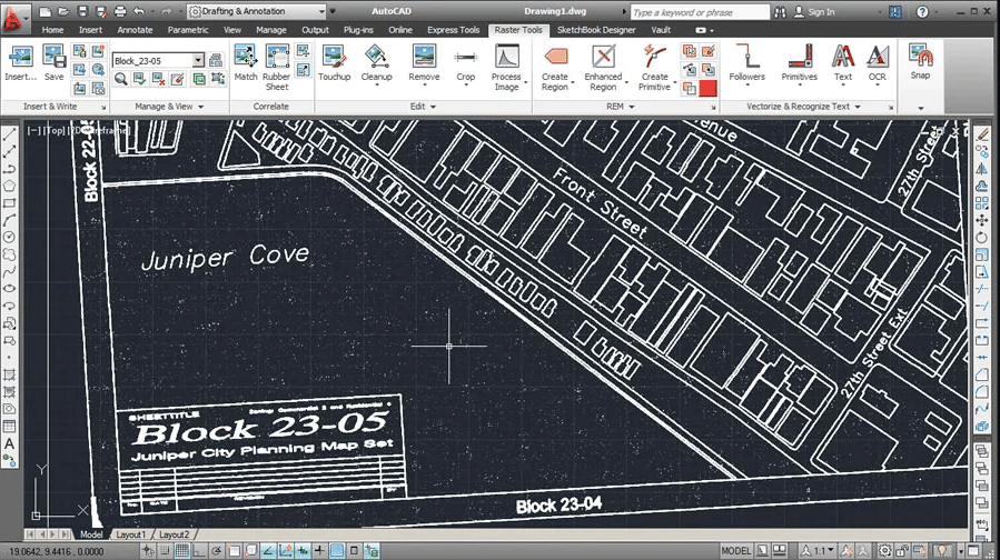
The Drawing Exchange Format (DXF) file is available as a universal format. This allows other programs to read and write the AutoCAD files.
This 2D file format is an ideal option for laser cutting purposes. It also gets along well with other programs. Remember to specify the thickness of your material when sending your DXF file to a third party.
DWG File Format
DWG is a CAD format written with binary and used in saving 2D and 3D data. This format is a proprietary CAD format owned by AutoCAD.
All third-party applications that are compatible with DWG format can access DWG files. However, we do not strongly recommend sending your CAD files in this format. This is because there are usually compatibility issues.
Other Proprietary CAD FIle Formats
There are other proprietary formats, and each CAD package has its distinct format. For instance, SolidWorks’ default file format is SLDPRT.
Proprietary CAD formats are great for exchanging 3D models within your team. However, it is essential to note that they are not suitable for exchanging designs outside your company. Other organizations may not use similar CAD software.
Although, there is the possibility of CAD software clashing. This happens when they are of different versions. For example, a person with a 2019 SolidWorks software license may find it difficult to open files sent from a user with a 2020 0r 2021 SolidWorks software license.
How to Convert CAD Files to CNC File Format?
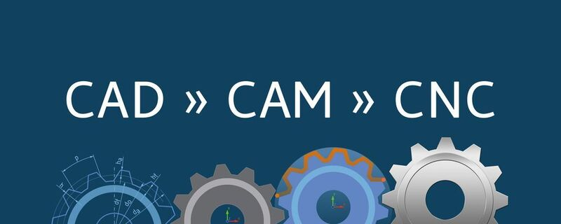
A wide range of formats comes to mind when working with CNC milling. However, to create a G-Code, one may end up using different G-code file types. This depends on the post-processor installed in the CAM software.
Therefore, this may call for a change in format type. Most CAD software help design 3D technical drawing. Unfortunately, the CNC machine does not know or read the 3D designs as a sequence of dimensions and shapes.
As a result, the 3D design needs to be changed or converted to a specific format (G-code files) for CNC routers to use. Converting CAD files to G-code requires CAM software. This CAM program is helpful since manufacturers do not have to practice the usual manual manufacturing process.
The CAM program handles the conversion by simply converting the data in the same CAD package to G-code files. The set of instruction plans (G-code) in the recipient machine helps to control the CNC machines. It gives instructions on when and how to rotate, cut or move, etc.
STEP format is the prevalent CNC machining file format used throughout three different machines. It is used in a standard manner. Many CAD software programs permit digital models exportation in STEP format. Likewise, multiple free online tools support CAD files conversion.
Getting a CNC Quote

Nowadays, it is more convenient to get your CNC parts made. To get a quote, you only need to upload your 3D design in a supported file format on web browsers. Once you have your CNC design files prepared, ensure you get a quote from a credible manufacturer.
After the quotation has been completed, the next thing is to start manufacturing. State your requirements, including the material of your choice, quantity preferred, and processing duration. If there are other additional manufacturing requirements not indicated, mention them.
AT Machining’s experts are always available and ready to bring the designs in your CAD files to live through quality products. We have technicians with years of experience in numerous manufacturing methods such as 3D design, laser cutting (Stereolithography), and CNC Machining. Contact us today, and let’s handle your next CNC project.
Conclusion
Designs made with a CAD package improve the quality of your products. This article gives you a tour of the various CAD formats compatible with CNC machining and how to apply them.
With the tons of manufacturing processes in use, it is easier to have your CAD transferred to a CNC mill after CAM software has rewritten it. Thus, a computer numerical control technology (CNC router) oversees the machine’s work and ensures you get the best results.
AT Machining experts have an excellent understanding of CAD models and file formats. Contact us whenever you have any inquiries.