跳到内容
跳到内容 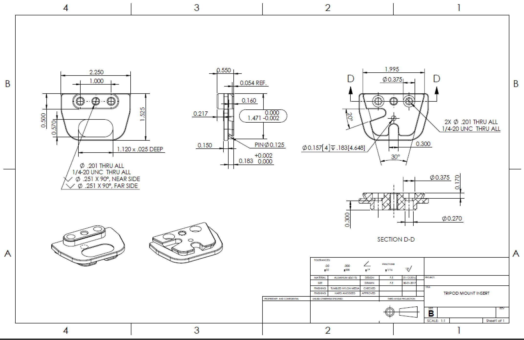
Known as the language of engineers and machinists, engineering drawings are vital to transferring ideas. Like every other language, there are key engineering drawings tips that make this transfer of information seamless and easy. For you as our reader and prospective customer, better engineering drawings can aid us in understanding your design intent in a much better way. It also helps reduce the cost of your CNC machined part by a great margin. There are plenty of tips and here are our top 10 picks.
#1: Drawing Line Rules
The foremost tip for drafting is to follow preset standards for drawing lines. Accurate depiction means cost and time saving for both ends. Let us make this pictorial and easy to understand!
Continuous Line
This is the most common line in drafting known as the drawing line. It serves a general-purpose and is used to signify the physical boundaries of objects. This line can exist in variable thicknesses depending on where you use them e.g., outer contours can use thicker lines while internal features can incorporate thinner ones.
Hidden Lines
It is always important to “feel” your drawings as if you are the layman viewing the drawing for the first time. It would help if you aimed to perceive the part in different views, and any feature not appearing directly in that specific view should be denoted by hidden lines. This engineering drawing tip is vital for accurate communication of design intent. An example can be an internal step in the part that hidden lines can show.
Centre Lines
Make the Drawing Eye-Pleasing by Centre Lines

Remember always to take advantage of centre lines in symmetric parts. It helps to reduce a lot of gritty dimensions and details, ultimately easing design communication.. They are also important in marking centres of holes and other circular features.
Break Lines
Imagine a driving shaft being 5000 mm long with dimensioning of keyways required only in the first and last 200 mm. It is wise to show dimensioning for relevant sections only and mark the rest of the shaft with break lines. This will signify constant diametral sections for the rest of the shaft thus saving space on the drawing paper for other vital views.
And last but not the least:
Cutting Plane
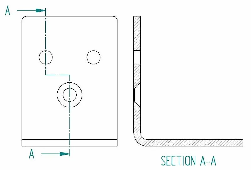
Cutout views work their magic to make your CNC machining service provider easily understand your part’s requirements. They comprehensively describe features that might otherwise be confusing with hidden lines.
With the drawing line rules covered, let us move on to our next engineering drawing tip!
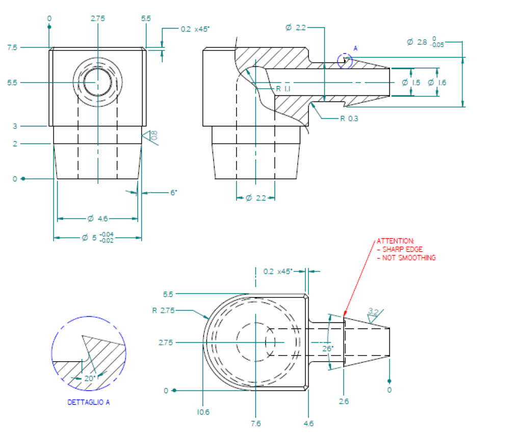
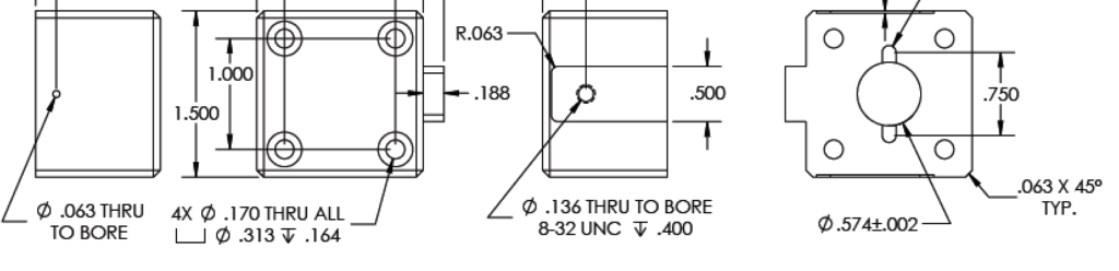
#2: Consider key dimensional features
Engineering drawing for CNC machining is a bit different. It would help if you considered dimensioning only key features. The 3D model shared with us helps us a great deal with the rest of the details. This ultimately helps save time subsequently allowing us to quote the most optimal price.
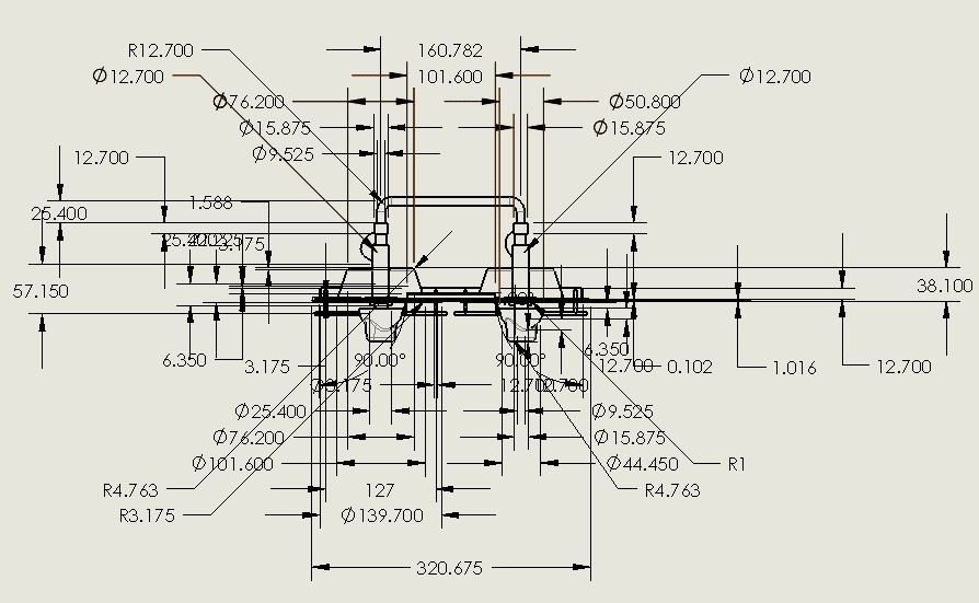
To start with, inspection details like datum references, callouts, tolerances, and threading information is vital for our working. As an example, the following image shows an example of what should not be done:
And this image shows what a concise yet comprehensive drawing looks like:
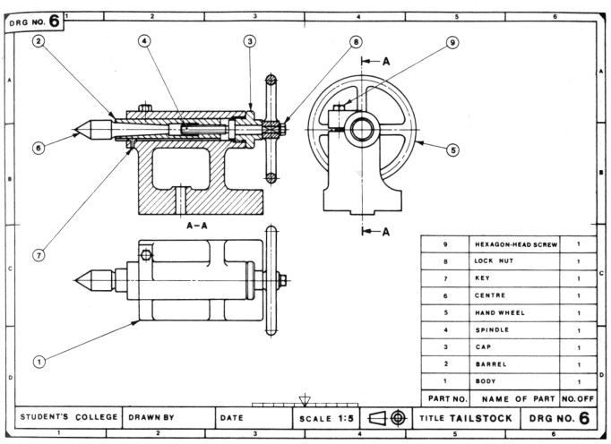
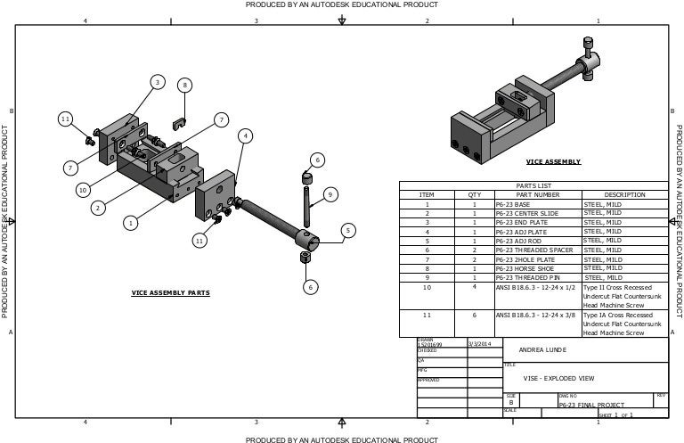
#3: Design for Assembly
Number 3 on our engineering drawing tips list is Design for Assembly. It will be really important to always denote your part if it is to be fitted in an assembly. Assembly instruction and assembly drawing with a parts list will do wonders for your machining needs. An exploded assembly view with a part list will be the icing on the cake. The following images denote an assembly drawing and exploded assembly view respectively.
It is also important to mention mechanical fitments on part drawings. For instance, slide fit, press fit, etc. must be mentioned on the specific mating features for accurate manufacturability. If any off-the-shelf components will be installed on your part, please always mention the relevant part number so that the machinist can look it up in the catalog.
We want you to have a hassle-free and plug n play experience for manufactured parts and assemblies.
#4: Depict hole tapping details
Two key dimensions for tapping are:
- Thread size
- Depth call outs
Measurement of thread depth is often not easy. Therefore, always mention the size and depth of every tapping location. And please treat the depth call-out as the minimum value.
Moreover, please always signify the side from which the depth needs to be measured.
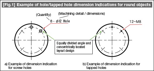
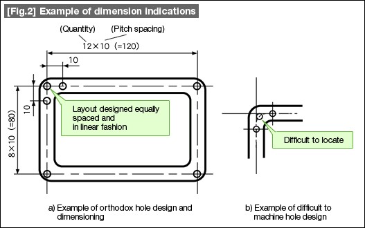
#5: Avoid Redundancy
Avoid redundancy in dimensioning to save precious space. This key engineering drawing tip helps to keep drawings relatively clean and makes the deliverable much more accurate. Redundancy in dimensioning of holes should be avoided especially when:
- Holes are at an equal angle from each other and located concentrically
- On straight lines at equidistance
The number of holes and their dimensions is indicated by a leader line, quantity, hyphen, and dimensions. This is particularly useful in dimensioning flanges where multiple holes all in a circular pattern are present. The following image represents an example of each.
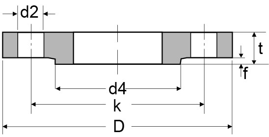
#6: Provide Practically Applicable Tolerances for Parts
While tolerancing in engineering drawings is always important, it must be noted that over-tolerancing your parts is not a good design intent for cost. Functionally critical features are the ones you would want our machinist to pay particular attention to. Over dimensioning and tolerancing your drawings is a disadvantageous technique.
Provide relevant tolerancing considering functionally critical areas. For instance, for a raised face flange shown in the figure below, tighter tolerances and surface finish requirements should be at d4 and f since these faces will directly mate with the connecting flange.
#7: Coordinate with your machining service provider
This is another point acting as a time and cost saver. Always explore your CNC machining service provider’s capabilities. The provision of engineering drawings with unfeasible tolerancing dimensions is a hassle for both the client and the customer. Therefore, always discuss and evaluate comprehensively with your service provider for the following four forms of tolerancing:
- Form
- Orientation
- Location
- Run-out
It is also important for you to evaluate tolerances based on the material. Achievable tolerances for plastic will definitely not match that of super duplex steel.
#8: Make various drawings of the same part
Many a time, the final deliverable part might go through multiple manufacturing stages. Let us take an example of an impeller. It might go through the following stages:
- Casting
- CNC Machining
- Coating
- Final surface finishing
In this case, you can imagine how much of a mess the drawing will be if details of all these procedures will be included in a single document. Therefore, multiple engineering drawings for the same part is a good idea for such cases. However, you must reference these drawings properly to make the step-by-step procedures clear to the machinist.
#9: Self-Explanatory Notes and Title Blocks
It is noteworthy to provide self-explanatory text above the title block for the machinist reference. For instance, every dimension is not necessarily accompanied by a tolerance value. In this case, the standard for general machining tolerances is to be provided in the text. For example, ISO-2768m denotes the standard to be referred to for general tolerancing and the letter “m” indicates the relevant tolerancing level.
Another example of useful notes is that of surface finishing. It is not viable to mark every contour with the required surface finishing. Therefore, marking the following in-text will serve the purpose of saving you space and time.
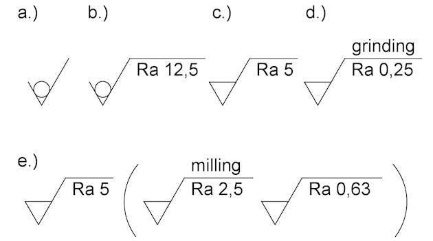
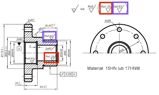
As you can notice in the image above, any surface in the drawing that does not have an individual roughness marking assigned, the reference preceding the bracket will apply.
For the title block, always present clear information for the machinist so that time is not wasted in clarifying basic information. For example, drawing number, 1st or 3rd angle of projection, reference drawing if any, scale, sheet number in case of multiple pages, material assignment, and drawing sheet size are important aspects.
#10: Standardize your drawings
Last but not least on our list, engineering drawings, like all other fields, have “genres” too. Drawings related to mechanical engineering parts should be drawn with the same standards across all platforms. This is similar to the standardization of languages to allow people across borders to understand each other.
Always remember that engineering drawings are means of communication. Civil engineering, architectural, Heating Ventilation and Air Conditioning (HVAC) all have their own presets.
Summary
Here is our attempt to sum up all of your learning with these initials:
T-Thoroughness: Leave no ambiguities. Ensure technically correct, accurate, consistent, and unambiguous engineering drawings.
B-Brevity: Quality over quantity! Don’t over-dimension and ensure not to waste page space. Always provide notes where needed and only put that on the drawings what needs to be on it.
C-Clarity: It is an important engineering drawing tip! Will the person interpreting my drawing be able to understand it from my view? Leave no room for misinterpretation by standardization of drawings.
C-Consideration: Always evaluate cost + time with required finishing of parts. Consider costing as a key element. If in doubt, consult your machining service provider before finalizing your budget.
Conclusion
With our top 10 picks of engineering drawings tips, the importance of this aspect should be quite evident. It is the language that links your ideas to practically producible parts. The ultimate goal is to capture maximum geometric details of products and assemblies.
What we offer is remarkable in its own right. Our expert line of engineers at AT Machining helps you along the design process by putting ourselves in your shoes. With extensive experience, we can save your time by capturing important details from the 3D model itself and providing you with real-time solutions to optimize incurred costs. For your machining and prototyping needs, you can contact us right here.