 跳到内容
跳到内容 Flatness GD&T: Complete Guide to Basics and Applications
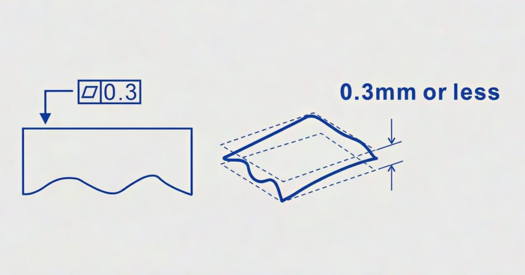
Flatness (GD&T) is an essential engineering tolerancing tool that design experts and engineers universally employ to control the shape or form of each feature in their mechanical parts designs. Form controls comprise four types of geometric tolerances, including cylindricity, circularity, straightness, and flatness.
This form tolerance is crucial in ensuring proper sealing, assembly precision, and optimal load distribution for peak functionality, performance, and overall longevity. Thus, it is essential to understand how to control flatness in manufacturing, especially to ensure the mechanical parts intended for assembly fit and align perfectly.
This article delves into a detailed discussion on everything you need to know about flatness in GD&T. We’ll also explain how to specify flatness callout on a drawing, how to apply flatness in GD&T, and standard tools and methods to inspect surface flatness. Let’s dive into the details!