跳到内容
跳到内容 
Understanding Tolerance in Press Fit
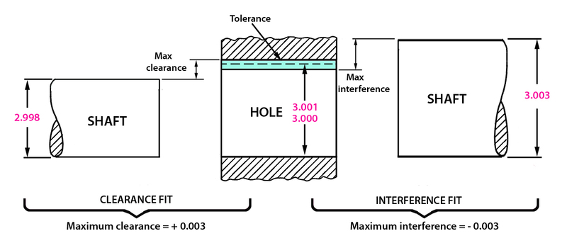
Understanding tolerance in press fit is essential to effectively design and manufacture two parts joined together by interference. However, tolerance is the acceptable deviation from the nominal dimensions or base measurement in engineering fit. Tolerance in press fit ensures the components of an assembly match the specified functional requirements without jeopardizing the joint’s integrity.
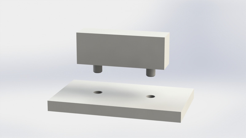
Unlike transition fit and clearance fit, interference fit forms a permanent coupling of two components. These friction fits (press fit) require light or large forces depending on factors like material properties. More so, tolerance in press fit is crucial since parts can be damaged easily due to significant differences in the mating dimensions.
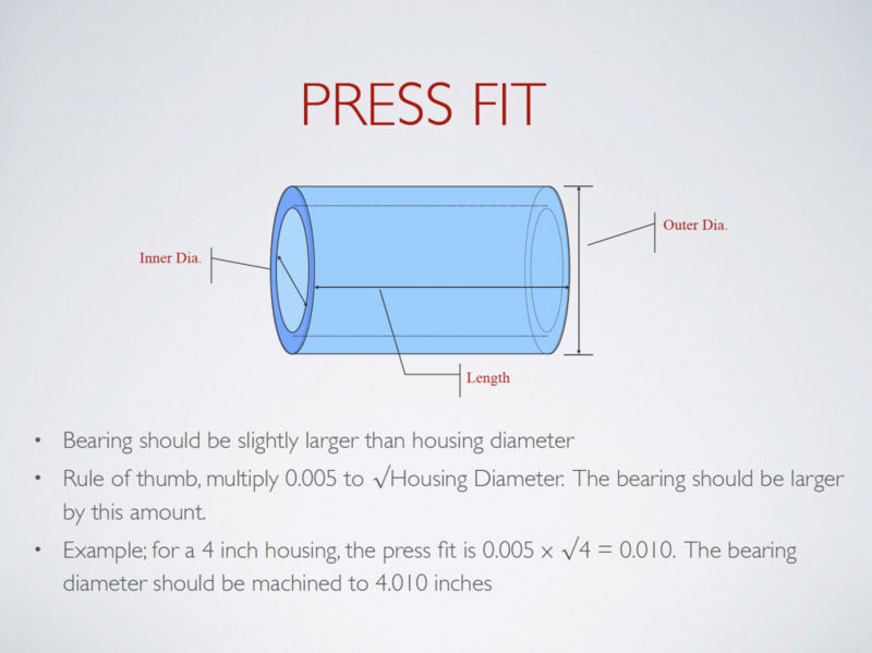
“Shaft basis system” and “hole basis system” are the widely used systems of defining the limits and fits of components in an assembly in engineering fits. For example, the hole diameter is often smaller than the shaft in the interference fit in a hole and shaft basis system. Hence, manufacturers use a mechanical or hydraulic press to force the shaft into the hole. You can also assemble press-fit components with cold pressing.
Why Is Tolerance in Press Fits Important?
Since inaccuracy is inevitable in manufacturing processes, tolerance plays a crucial role in defining a part’s maximum and minimum limits. Tolerance in press fit facilitates the smooth and tighter fits of interchangeable parts from different sources. Also, it ensures the proper functioning of the press-fit assembly, providing strength, load-carrying capacity, and better alignment.
Key Factors Influencing Tolerance in Press Fits
Although tolerance in press fits is essential to ensure the parts in an assembly form a secure and reliable connection, various factors may influence this tolerance. Here are the common ones:
Material Properties and Their Impact

The material properties such as elasticity, hardness, yield strength, coefficient of thermal expansion, and surface finish significantly influence tolerance in press fits. The softness or hardness of a material affects its performance in an assembly. Softer materials allow a loose fit since they offer better mechanical deformations during assembly. In contrast, harder material usually results in a tighter fit because it often resists deformation.
The coefficient of thermal expansion (CTE) often varies in CNC machining materials. As such, dimensional changes like temperature fluctuation may occur because of incompatible coefficients of thermal expansions between the mating parts. Therefore, it influences the tolerances in press fits.
The elasticity of a material determines how much it can deform under stress. A material with high elastic moduli straightens back after assembly, enabling a more stable interference fit. A material’s yield strength is a critical factor influencing press fit tolerance. It would help to note that permanent deformation may occur due to applying excessive force beyond the yield strength of the press fit material.
Temperature and Environmental Conditions
Environmental factors, including temperature, thermal cycling, assembly environment, humidity, and corrosion, often influence tolerance in press fits. Temperature often causes thermal expansion and contraction in materials. As such, extreme temperatures may affect the tolerance of press-fit components significantly.
Other environmental conditions, including assembly environment, humidity, and corrosion, may influence the material’s surface conditions, altering the interference fit components’ dimensions. Humidity alters the properties of the press-fits material, while corrosion affects the dimensions of the press-fits.
Measuring and Calculating Tolerance for Press Fit
Product engineers often utilize various measuring tools with precise calculations to achieve and maintain great tolerances in a press fit. Moreover, high accuracy in press fit components ensures the reliability and peak performance of the assembled parts. Here are tools and techniques used in measuring and calculating tolerances for press fit
Tools and Techniques for Accurate Measurement
Machinists and product engineers utilize various tools to ensure accurate measurement in press fit design. Standard tools used include:
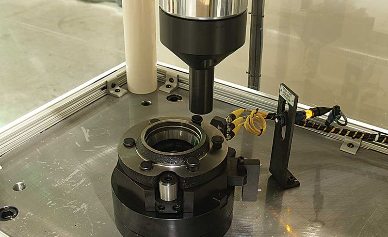
- Coordinate measuring machines (CMM): CMM is a high-precision measuring tool for measuring critical tolerances and complex dimensions in interference fits.
- Gauges and plug gauges: Go/no-go gauges are often used to measure hole tolerance.
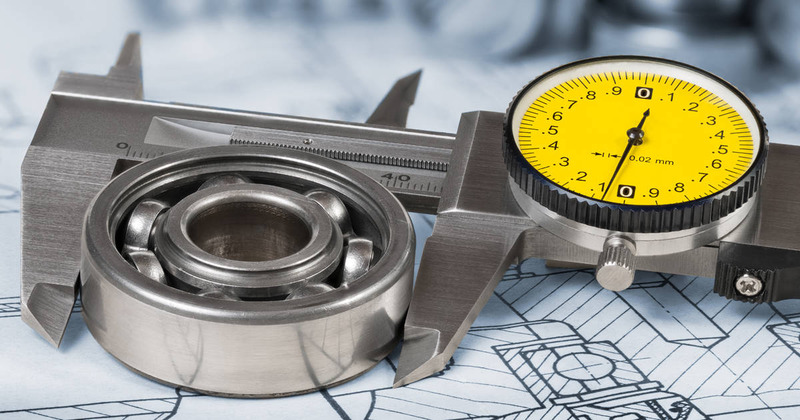
- Micrometers and calipers: For accurate reading of dimensions of press-fit components, including lengths, diameters, and depths.
- Optical measuring systems: These systems employ cameras and high-end image processing algorithms to measure sizes without direct contact.

Standard techniques used in measuring and calculating tolerances for press fit:
- Ultrasonic Thickness: Manufacturers use ultrasonic mechanisms to measure the thickness of materials. It helps identify the deformation and changes in press fit components during assembly.
- Interferometry: Interferometric methods use interference patterns of light waves to measure/calculate distances and surface profiles with higher precision. It is commonly used to determine minute variations and deformations in press-fit components.
- X-ray and CT Scanning: This measuring technique is commonly used to inspect the internal views of press-fit assemblies to check for defects or misalignments.
Calculations for Predicting Press Fit Tolerance
Product engineers and manufacturers often use different calculations to determine how much interference an application requires. Here are some of the calculations:
Clearance Fit Calculation: This calculation is commonly used in predicting greater clearances, allowing the press-fit component to be easily assembled.
Interference Fit Calculation: Product engineers employ mathematical models in predicting the required interference fit for a press fit. This calculation involves examining factors such as the preferred level of interference, components’ dimensions, and material elastic modulus.
Thermal Expansion Calculations: This calculation helps to determine the dimensional changes in the material due to large temperature variations. Moreover, it is effective in adjusting the initial dimensions for interference fits that will be subjected to temperature exchanges.
Material Properties Considerations: Engineers consider material properties in determining press fit tolerances, ensuring that the components are within the material limits.
Tolerance Stack-Up Analysis: This is a systematic method of predicting the cumulative effects of press-fit components in an assembly. It helps to determine the overall tolerance of a press-fit assembly, preventing the possibility of unacceptable variations in individual part tolerances.
Finite Element Analysis (FEA): It is helpful in modeling and predicting the performance of press-fit components under varying loading conditions. As such, you can easily improve the design for the preferred press-fit tolerance and functionality.
Challenges in Achieving Optimal Tolerance
Various challenges/setbacks hinder manufacturers from achieving tight tolerances in press-fit design and manufacturing methods. Here are some of them:
Common Pitfalls and How to Avoid Them
Inaccurate Measuring Tools
Using less accurate measurement tools is one of the common pitfalls of achieving optimal tolerance in press fits. It results in an inaccurate assessment of the tolerances and dimensions, resulting in a deviation from the desired tolerance.
Solution: Use high-precision measuring tools and equipment, calibrate regularly, and verify measurement with multiple processes to ensure accuracy.
Poor Material Analysis
Unexpected challenges may occur as a result of not analyzing the material properties. This is because variations in material properties can hinder the performance of press fits even within the specified tolerance ranges. Differences in hardness or elasticity can cause unanticipated assembly results.
Solution: Thoroughly analyze material properties by testing its harness and accounting for variation in the design and tolerance calculations.

Inadequate Tolerance Analysis
Failure to perform a comprehensive tolerance analysis can result in unpredicted behavior during interference fits. Besides, tolerance stack-up can result in variations exceeding the acceptable range, especially in situations where individual part tolerances are amassed in an assembly.
Solution: Manage and reduce tolerance accumulation efficiently to achieve optimal tolerance in press fits. Use tolerance stack-up analysis and thorough simulation to detect potential defects and ensure the preferred tolerances.
Manufacturing Process Variations
Lack of control in manufacturing processes is a significant setback in achieving optimal press fit tolerances. It leads to unreliable press fits due to variations in machining and heat treatment.
Solution: Implement strict process controls, observe manufacturing parameters, and set up quality assurance systems to achieve consistent results.
Case Studies: Lessons Learned from Real-world Applications
This section discusses different setbacks in achieving optimal press fit tolerances in mechanical applications:
Aerospace Bearing Applications
Aerospace assembly with press fits in its structural components had different variations in tolerance, raising concerns about long-term safety and reliability. Engineers employed Finite Analysis (FEA) in simulating the occurrence of stresses and deformation.
More so, this analysis indicated potential areas of concern. At the same time, modifications were made to the design to ensure the press fit tolerances could handle the calculated loads and conditions of the working environment.
Automotive Assembly
Assembly difficulties, such as variations in the hardness of press-fit components, may arise due to variations in heat treatment processes. There have been instances of variation in engine performance due to failure of the press fits to meet the specified tolerances in the assembly of engine components. As such, engineers discovered through a comprehensive evaluation that variation in the shaft material’s hardness is responsible for inconsistent press fits.
However, implementing strict quality control procedures in heat treatment processes and performing thorough material analysis helps to achieve consistent material properties.
Electronics Enclosure Manufacturing
Assembly misfits tend to occur in electronic enclosure components due to inadequate consideration of thermal expansion during temperature variation. Product teams conducted a thorough evaluation and identified that the selected materials possess varying coefficients of thermal expansion, leading to dimensional alterations during changes in temperature.
As such, it is advisable to include thermal expansion calculations in the design phase and choose materials with the coefficient of thermal expansion that matches the press-fit application.
Precision Bearing Manufacturing
Press fits sometimes fail to meet the preferred tolerances in precision bearing production, affecting the overall performance of the bearing. However, real-time monitoring of the machining process and incorporation of in-process measurements help to detect and correct errors immediately. Consequently, this proactive approach effectively maintains press fit consistency when manufacturing precision bearings.
Best Practices for Tolerance in Press Fit Design
This section explores some of these best practices help to achieve the specified tolerance in press fit designs:
Design Considerations for Reliable Assemblies
Here are some design considerations for reliable assemblies of press-fit components:
- Use materials with compatible elasticity, hardness, and thermal properties to ensure the tight tolerance of the interference fits.
- Conduct tolerance stack-up analysis to examine how the tolerances of individual parts interact and ensure the collective effect is within acceptable limits.
- Adjust the design to match the requirement of the intended application, deciding whether clearance or interference fits are required.
- Use materials and clearances that can handle the expected environmental conditions for your press-fits design. It helps to maintain the specified tolerances over the product’s lifespan.
- Employ surface finishes to mitigate friction and lubricants to ease assembly while maintaining the preferred tolerance.
- Include design features like chamfers or tapers to allow easy assembly and disassembly of press-fit components.
Tips from Industry Experts
AT Machining experts recommend real-time monitoring during manufacturing to identify and correct potential errors immediately. In-process measurements and quality inspections must be incorporated to ensure desired press fit tolerance and quality.
Practicing iterative prototyping and testing to improve press-fit designs would be best. As such, you would learn from each prototype, improve quality, and test again to derive the ideal press fit for the intended application.
Also, industry experts advise collaborative efforts between the design, materials, and manufacturing teams. This cross-functional alliance is crucial to achieving a comprehensive approach to press fit design.
Nevertheless, industry experts recommend continuous learning and adaptation in new technologies and materials as it is beneficial to achieving ideal tolerances in press fits.
Professional Services for Tolerance Press Fit
It is advisable to consider all factors to determine the ideal press fit tolerance. However, whenever you need the help of professionals in determining the optimal tolerance for your press fits, AT Machining is the perfect manufacturer offering professional services.
AT-Machining is a top ISO-certified CNC shop offering professional manufacturing services, including tolerance engineering, CNC precision machining, rapid tooling, and 3D printing. We pay attention to the design requirements of your fits. Our well-trained and experienced experts leverage our state-of-the-art CNC machines and machining capabilities to handle your special requirements. Submit a CAD file now; we offer instant quotes!
Conclusion
Tolerance plays a significant role in designing press fit, ensuring the assembly’s reliability in intended applications. However, it is essential to understand the potential factors influencing tolerance press fits, tools and techniques used in calculating tolerance in press fits, and potential challenges in achieving optimal tolerance in press fits.