跳到内容
跳到内容 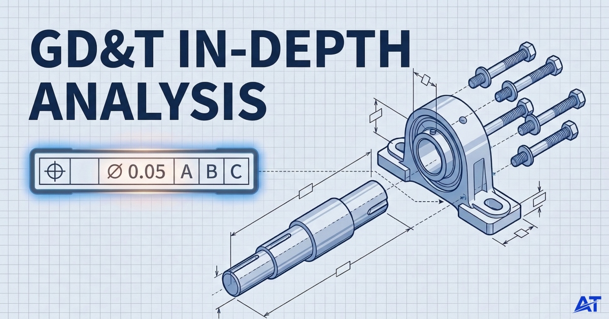
What is GD&T?
GD&T is a system of characters, symbols, and standard dimensions used by manufacturers and engineers to convey design intent. It defines a part’s characteristics and permitted variation from its true or ideal position. GD&T’s objective is to emphasise a part’s key characteristics and show how they relate to the larger picture.
Geometric dimensioning and tolerancing covers both a component’s geometric dimensions and its tolerance values. The minimum and maximum limits of deviation for a given dimension are indicated by a part’s tolerance. Establishing appropriate tolerances will enhance the quantity of correctly machined parts and optimise the product approval rate.
Product teams should establish tolerances with as much flexibility as feasible while preserving product functionality because tighter tolerances are more accurate but can increase production costs.
GD&T makes it possible for everyone to read and comprehend the measurements of a component. This is crucial for producing accurate and useful parts. GD&T uses the same procedure for all manufacturing processes, including injection moulding, CNC machining, and additive manufacturing. Nonetheless, some GD&T features will be more pertinent to some approaches than others.
How Does GD&T Work?
Everyone working on technical drawings, from design to machining, is guaranteed to speak the same language thanks to GD&T. Geometric features like flatness, straightness, cylindricity, roundness, perpendicularity, parallelism, angularity, position, profile, concentricity, and symmetry (among others) make up their vocabulary. These various geometric features are grouped into various tolerance categories (such as form, orientation, location, and runout) and utilise datums (such as point, line, plane, and volume) as a point of reference to which other components of the part’s composition can be connected.
Misunderstandings between those in research and development (R&D), who design the part, and those who read and interpret the technical drawing in the machine shop can result in significant financial waste. As a result, GD&T’s consistent and logical terminology aids in comprehending the geometric properties and tolerances of the part. It ensures constant geometries throughout design and manufacture, minimising uncertainty and interpretation while providing consistency and convenience.
Designers, engineers, and technicians must rely on the most precise and dependable communication because today’s designs are ever more complex and advanced. GD&T saves time and improves the efficiency of the design and manufacturing processes by facilitating clear and effective communication among team members.
Categories of GD&T Symbols
GD&T has five main categories. Each of the five tolerance types (form, orientation, location, profile, and runout) describes how much variation from a specified maximum limit is acceptable for individual feature sizes as they relate to the specifications.
Form Tolerances
Form tolerances control defines the degree of deviation from the target shape of individual feature areas without reference to other shapes or reference points (datums). Form tolerances ensure that the shape of a feature maintains its intended shape for consistent dimensional control and to reduce rejects due to dimensional quality problems. Examples of form tolerancing include:

- Flatness: It ensures a planar surface is maintained uniformly flat for all points on the flat surface and that no point exists outside of the defined varying distance between two parallel planes.
- Circularity: It controls the roundness of circular axis features, such as a cylindrical surface.
- Straightness: It ensures that the entire length of a straight edge maintains its axis straightness along its entire length. It helps with straightness control.
The use of form tolerances guides the allowable shape for each feature area. It also guides the amount of machine allowance available for production processes for each feature area within manufacturing limits.
Orientation Tolerances

Orientation tolerance control determines the tilt and alignment of features with respect to a datum reference feature. They are essential for the proper assembly and functioning of parts that share multiple functional features. Some common tolerances of orientation include parallelism, perpendicularity, and angularity.
Orientation tolerances apply to either surface elements, feature surfaces, or two parallel surface elements. For example, parallelism ensures the surface or line in question is parallel to the associated datum plane (or datum axis). Angularity indicates that the surface or parallel line will be at a specified angle to the associated datum.
Location Tolerances
Location tolerance control where a feature is located relative to one or more datums. It ensures that the features of a part are properly located for assembly or operating purposes. Location tolerancing may consist of two primary types: position and concentricity. These types of tolerances may be represented using either cylindrical tolerance zones or circular features.
A primary datum, a secondary datum, and a tertiary datum are used to provide references with respect to the control of location. They are also used for the implementation of statistical process control (SPC) and the reduction of assembly failures.
Profile Tolerances
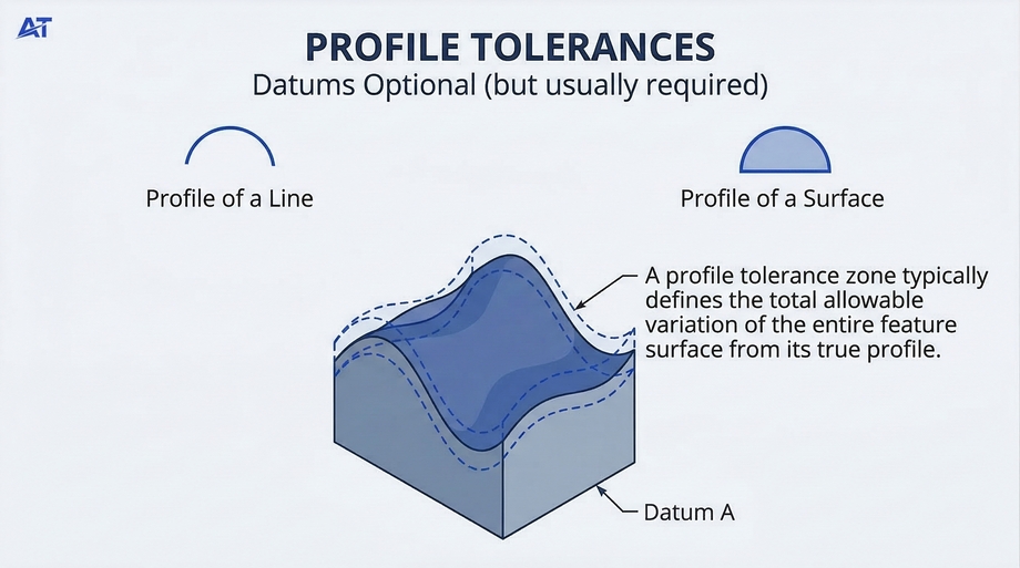
Profile tolerances govern a feature’s shape in relation to a datum, or independently. They can be line profiles (where a section of a feature is controlled) and surface profiles (where the complete surface of a feature is controlled).
Profile tolerances are commonly applied to complex parts and outer surface features, assuring that the design intent has been satisfied at all measured locations. In addition to providing flexibility, profile tolerances provide precise control over the geometrical characteristics of a component.
Runout Tolerances
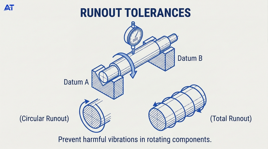
Runout tolerances are used to control both functional and rotational accuracy of a feature. Runout tolerances are essential in maintaining precision manufacturing through CNC Machining and provide a means for reducing the number of defective components due to rotation or motion. These tolerances are primarily used on rotating components. They can be:
- Circular runout: It measures the deviation of a rotating feature from its intended circular path about a datum axis.
- Total runout: It measures deviation across the entire surface of a feature about a datum axis, which assures that parts will operate smoothly together when assembled.
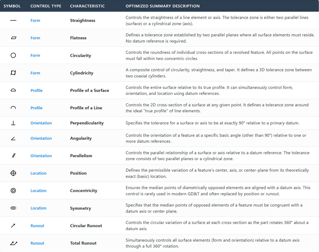
GD&T Symbols Reference Guide
Below are the common symbols for GD&T:
What is Feature Control Frame (FCF)?
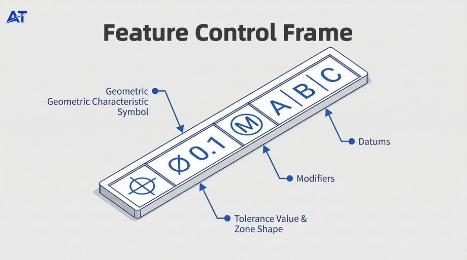
A Feature Control Frame (FCF) is a rectangular symbol used in geometric dimensioning and tolerancing (GD&T) to define the specific geometric tolerances that apply to a part feature. A feature control frame appears on engineering drawings and communicates the required geometric control clearly and unambiguously.
A feature control frame includes a geometric characteristic symbol, a tolerance value, and a tolerance zone defined. The following possibilities can occur:
- M denotes that the tolerance is applicable in the Maximum Material Condition (MMC), and L denotes that it is applicable in the Least Material Condition (LMC).
- U denotes an uneven bilateral tolerance, such as minus 0.20 and 0.80 for a tolerance of 1 mm.
- P denotes that the tolerance is measured at a given distance from the datum in an anticipated Tolerance Zone.
- Regardless of feature size, no symbol installs the tolerance (RFS).
Application of GD&T in Manufacturing
Here are the different applications of GD&T symbols in machining and designs:
GD&T in Engineering Drawing
To ensure that the vendor is manufacturing precisely what the customer’s design specifies, the engineering drawing acts as a check and balance. When it comes to accuracy, a precision tolerance of +/-.002 makes using GD&T cylindrical to the closest even more crucial. For cylinders that must be “cylindrical,” 0003 is necessary. For instance, you may quickly get up and running with it in this situation.
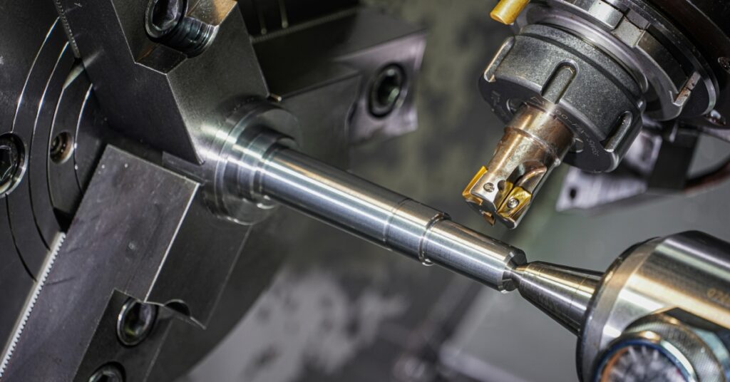
GD&T in CNC machining

The capacity to create items with extremely tight tolerances is one advantage of CNC machining. This is made feasible by the computer-controlled cutting tools, which enable extremely accurate movements. It is essential to employ appropriate GD&T to fully utilise this capacity.
GD&T symbols is used in CNC machining to define the tolerances for every part dimension. This guarantees that the final product will fulfil the design specifications. The position of features on the part, including holes and slots, is also specified using GD&T. This helps to guarantee that the features are accurately aligned and machined in the right place.
GD&T in 3D printing
As technology advances, the usage of GD&T in 3D printing is growing in popularity. This is because it offers a more realistic depiction of the final product, which can be quite useful when producing complex used parts.
GD&T symbols need to be utilised with precise measurements to be effective. Because 3D printing is an additive process, the finished product is constructed layer by layer. If GD&T is not applied properly, this could result in errors in the finished product.
Throughout the product development process, many engineers and product designers use 3D printing for rapid prototyping and tooling to produce affordable prototypes and unique components that would otherwise need significant tooling spend.
Since 3D printing is a single automated process, tolerances in 3D printing are different from those in standard manufacturing equipment. Tighter tolerances may save a significant amount of time and money during prototype and manufacturing, but they also need more work at the design stage.
Datums Feature and Datum Reference Frame

With 30 years of CNC experience, Sam is dedicated to solving complex design and machining challenges, ensuring precision and efficiency for every customer project.
[email protected]Best Practice for GD&T
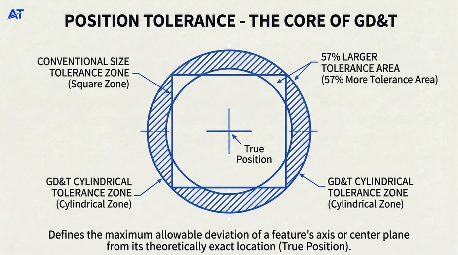
Use position tolerances instead of coordinate dimensions for holes. This creates a circular zone, providing 57% more allowable tolerance area while maintaining the same functional fit.
Contact Our CNC Machining ExpertThe process of selecting the individual detail in GD&T begins with identifying the features that will become the primary, secondary, and tertiary datum features on the part based on how they are used functionally, and defining where they are set off of functionally. A datum can be defined as a theoretically exact location or axis, line, plane, or combination thereof, based on a theoretical datum feature simulator that embodies all of the possibilities and can be evaluated at any time using these theoretical methods.
The relationship between the datums and the datum features gives dimensional tolerances on engineering drawings. This the reference points needed to provide engineers with the ability to measure their part’s tolerance using the datum. The datum reference frame (DRF) consists of three mutually perpendicular intersecting datum planes that collectively form a shared orthogonal coordinate system for measurements.
This coordinate system, or DRF, is then used to evaluate whether or not an engineering drawing’s geometric tolerances are within tolerance by using the primary, secondary, and tertiary datum of the component’s DRF. In an engineering drawing, the primary datum(s), secondary datum(s), and tertiary datum(s) are referenced in order from left to right in the feature control frame.
Establishing an orientation and position is done with the help of datums. They allow control via tolerance for orientation and location for features against others. If there is no datum reference frame constructed correctly, the feature control frame will not satisfy the intent of the design.
Tolerance Zone in GD&T
The purpose of a tolerance zone in GD&T is to establish the acceptable limits of variation that exist for a specific part feature, and to create a control around the allowable amount of variation in size, shape, or orientation within a part feature, to ensure that it fits and functions properly in an assembled state. Tolerance zones can come in many different forms, depending upon the type of geometric tolerances that are specified.
Flatness and straightness tolerances are created by establishing two parallel planes that control the variation of surfaces or axes. Cylindrical tolerance zones control the roundness of a feature, or feature (hole), and are typically applied to cylindrical features and cylindrical surfaces.
Projected tolerance zones are typically applied to features needing to maintain a specific orientation (location) above the surface of the part. Tolerance zones may use a centerline or other derived center points to control features with a high level of precision.
By clearly defining a tolerance zone, manufacturers can provide tight tolerancing on the part, with ample flexibility in the design process, while also working to reduce defects and improve the quality control.
Material Condition Modifiers

Material Condition Modifiers are the components used in Geometric Dimensioning and Tolerancing to provide a means of expressing the relationship between tolerances and the size of features. The most common MCMs are Maximum Material Condition (MMC) and Least Material Condition (LMC).
MMC tells us that the feature has the most material possible (i.e., the smallest hole or the largest diameter). LMC tells us that the feature has the least material (i.e., the largest hole or the smallest diameter).
By allowing for MCMs, you can provide bonus tolerance (i.e., an increase in geometric tolerance) when a feature is outside the maximum or minimum limits imposed by MMC or LMC, respectively, allowing for greater flexibility in manufacturing while maintaining precision for Feature Control Frames (FCFs) and Engineering Design Tolerances (EDTs).
The use of MCMs increases quality control, decreases production costs, and increases the efficiency of both the CNC Machining and inspection processes. MCMs are essential to controlling feature size and allowable variation, in addition to overall geometric control in GD&T.
Conclusion

You can use GD&T as a contemporary method to define your design’s dimensions and tolerance. It is better than the conventional plus/minus tolerancing, which does not ensure that the parts will be efficient when incorporated into a bigger compartment.
It is a well-recognised symbol that, when used correctly, can lower the expenses and time needed for a particular design. GD&T is necessary if you want to be sure that the components’ design will fit precisely for the purpose for which they are intended.
For companies seeking reliable precision and consistency, partnering with experienced providers like AT-Machining ensures that GD&T principles are correctly applied in CNC machining and inspection. Request a quote today!