Skip to content
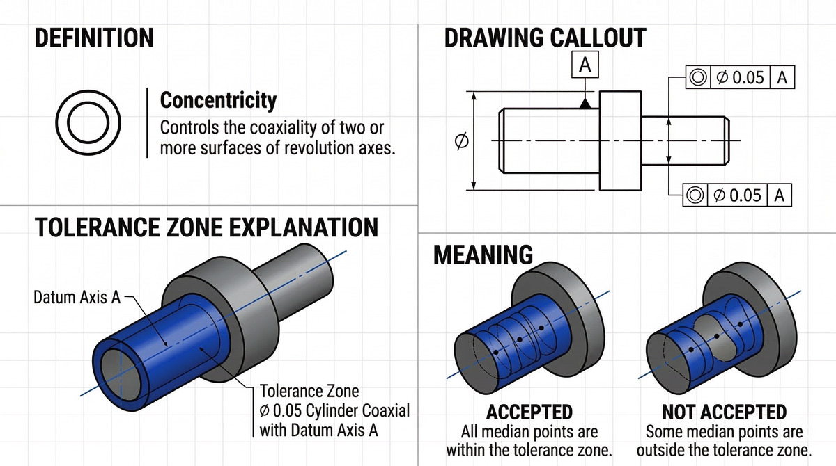
What Does Concentricity Mean?
Concentricity refers to the tolerance that controls the referenced feature’s derived median axis (or median point), to the datum axis. The term concentricity has a slightly different interpretation in GD&T compared to the general meaning most engineers know. Concentricity callout in GD&T ensures that the midpoint/central axis of two diametrically opposite points aligns within a specified tolerance zone.
Dynamic balance (balanced mass distribution) at the central axis must be uniform, even though the spherical or circular feature possesses surface variations, including notches or dips. Uniform mass distribution around the central axis and balanced rotation are critical requirements in high-speed rotating parts to prevent the risk of uneven wear and oscillation.
For most mechanical parts to operate satisfactorily, they often require incredibly accurate concentric designs. Parts such as tubes exposed to high pressure need a design with uniform wall thickness to avoid potential weak structural points. Concentricity as a 3D GD&T callout ensures that one or more features of a part are concentric about a datum axis.
However, concentricity is a complex tolerance to measure correctly during manufacturing since it hinges on measurements from the derived axis as opposed to a feature’s axis or tangible surface.
Many product engineers, machinist and measurement technicians find concentricity unnecessarily complex. For this reason, they rely on simpler callouts like total runout, circular runout, profile or position tolerance wherever possible, reserving concentricity for parts that undergoes high speed rotation or require an extremely high precision to function properly. Transmission gears are a good example in this instance because it requires concentricity to assemble the axes correctly and ensure coaxiality to prevent oscillations and wear during operations.
Concentricity Tolerance Zone
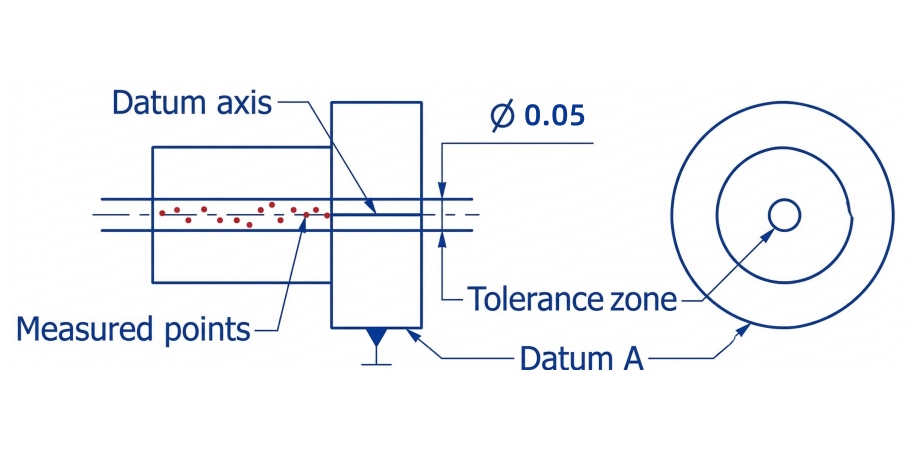
Product designers and machinists define GD&T concentricity with a cylindrical tolerance zone. It specifies a datum axis used as a reference point to establish the zone for GD&T concentricity. The permissible tolerance value for the callout is the diameter of this cylindrical zone.
You must calculate the midpoints of diametrically opposed points to determine the actual median axis for the part, ensuring concentricity. The median axis emerges from the resulting line when all median points are connected. Every point along the median axis must align within the cylindrical tolerance zone before the part can meet the requirements.
How to Measure Concentricity
Most expert designers and inspectors often avoid concentricity like the plague due to the measurement process involved. Taking the necessary measurements for concentricity can be challenging, costly and time-consuming.
When measuring, you need to connect the median points of the successive circular cross-sections to build the part’s actual central axis. For this reason, it would be best use a coordinate measuring machine (CMM) or alternative computer-aided measuring methods like a laser micrometer with a concentricity extension or an optical shaft measuring system to achieve a reliable concentricity measurement.
Oftentimes, engineers rely on a dial gauge to measure the difference between the lowest and highest points on the surface. Doing so, they mistake measuring runout for measuring concentricity. Even though it is often rare, the measured section must be a perfect circle for a runout and concentricity to be equal. Moreover, inspectors passing runout measurements as concentricity tends to introduce circularity errors in concentricity tolerance.
Measuring Concentricity Using a CMM
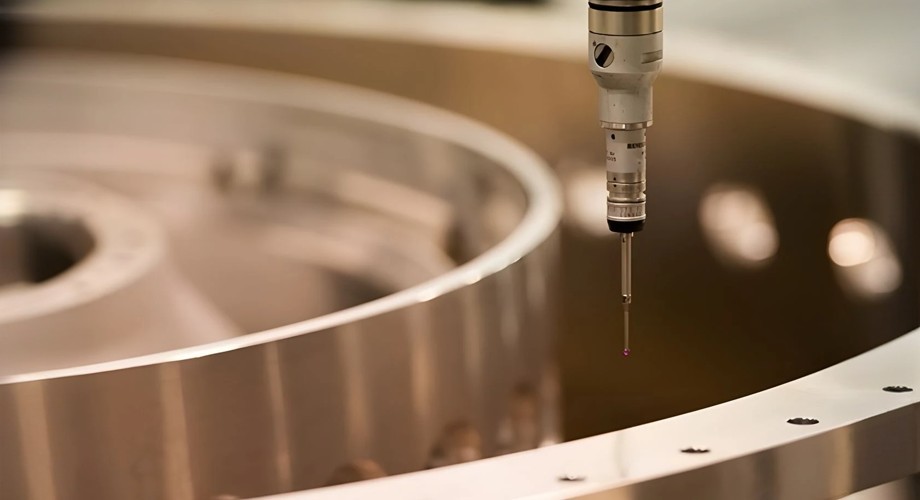
Let’s consider the step-by-step process for measuring concentricity with a coordinate measuring machine:
STEP I: Secure the Part and Fix the Datum Axis
Firstly, secure the part tightly in a suitable position to restrict any form of movement. Ensure the chosen position permits easy assessment of the entire cylindrical surface because there won’t be room for repositioning during the process of computing the measurements.
Then, you need to identify the datum axis. Inspection experts often choose the bearing end of a shaft for the datum axis because it directs the rotation of the assembly.
STEP II: Find the Median Point for One Cross-Section
Here, you need to use a CMM stylus to determine the control surface. Identify at least three pairs of diametrically opposed points at each cross-section of the cylindrical part. Except for some points that coincide, these pairs of points should create three distinct median points. Then, proceed to choose the average of the three median points to determine the appropriate median point for the cross-section.
STEP III: Repeat for Multiple Cross-Sections across the Cylindrical Part’s Length
In this step, calculate the median point for each cross-section on a cylindrical part. You should obtain the part’s measured axis or actual central axis when these points connect. It is also called the derived axis.
STEP IV: Examine If the Measured Axis Falls within the Specified Tolerance Zone
Check the position of the measured axis of the cylindrical part in reference to the datum axis after you obtain it. Each point of opposing elements on the axis must fall within the specified cylindrical tolerance zone in the feature control frame (FCF).
Concentricity GD&T vs. Other GD&T Symbols
Concentricity is an integral callout in specialized applications where uniform mass distribution is a priority. However, it is necessary to consider alternative callouts for concentricity wherever necessary to avoid the high cost and complexity of its application.
The 2018 ASME Y14.5 standard strongly favors other GD&T symbols, such as true position and circular runout, as suitable alternatives for concentricity in several applications without sacrificing the required specifications.
Concentricity vs. True Position
In GD&T, true position (sometimes called ‘position’) is a relatively simpler callout used to specify the size and position of different features. In most situations, a true position callout serves as a perfect substitute for concentricity, particularly for axis location. Positional tolerances and standard hole sizes are prioritized over concentricity when a precise mass distribution is not necessary.
Concentricity vs. Circular Runout
In GD&T, they are both closely related geometric tolerances utilized in examining the coaxiality and circularity of spherical or cylindrical features. The process of determining the derived median of a part renders concentricity a challenging characteristic to measure. Without using a computer, there is no alternative method to carry out a reliable calculation.
Since circular runout is a tangible feature, you can easily achieve accurate measurements from the part’s surface using simple instruments like a V-block and a dial indicator. Hence, substituting runout with concentricity requirements can significantly save cost and time.
Concentricity evaluates a cylindrical feature to determine how well it is centered on a theoretical axis. On the other hand, runout evaluates a feature’s circular path to determine the extent to which it deviates from a perfect circle precisely centered on an axis of rotation.
Runout often refers to the sum of concentricity and circularity. Runout tolerance is often equal to concentricity tolerance if a part is perfectly round. More so, you can use specially designed gauges to measure runout easily and in a relatively inexpensive way. Therefore, runout should be utilized wherever possible to assess surface shape for functional rotation control.
Concentricity Feature Control Frame (FCF)
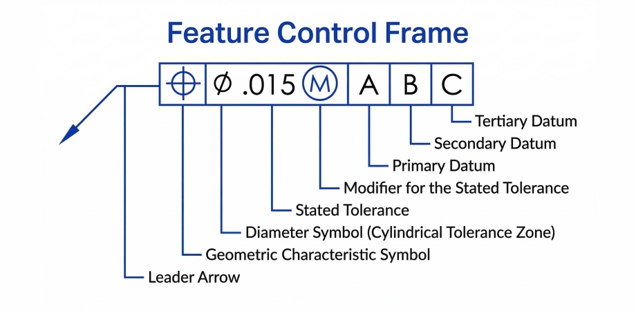
In this section, we will discuss feature control frames (FCF) to understand the controls, manufacturing conditions, and tolerances included on a part feature. In many cases, a single part may possess multiple features with GD&T tolerance, and each toleranced feature is represented by an individual feature control frame. Design engineers use a leader arrow to connect the FCF to the controlled feature or its extension line.
The GD&T concentricity feature control frame is fairly straightforward. It contains three distinct blocks, each of which provides information on different aspects of the GD&T. These blocks outline the requirements for concentricity and stipulate that, “relative to datum A, all center points of opposing elements on the cylindrical surface must fall within a cylindrical tolerance zone of 0.03.”
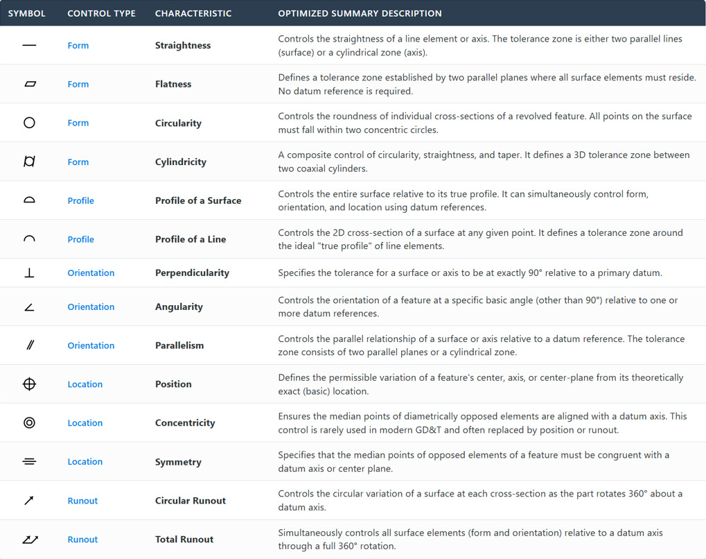
Geometric Characteristic Block


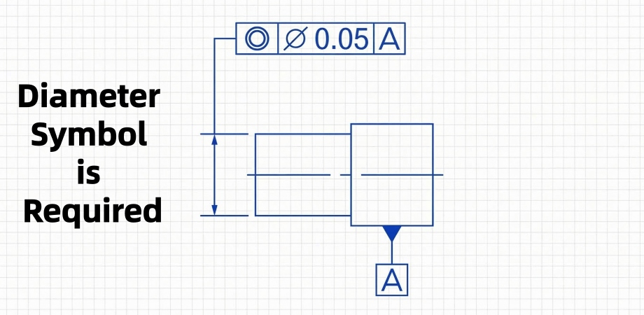
The geometric characteristic block is the first section in the concentricity feature control frame. It entails the symbol of the geometric tolerance applied to the part feature. The concentricity symbol is made up of two concentric circles and is placed in the geometric characteristic block to specify the required tolerance.
Feature Tolerance Block
It is the second block in the FCF, containing information about the size and type of the applied tolerance zone. The zone is often cylindrical in the case of concentricity and regarded as a diametral tolerance zone. Design experts use the diameter symbol to specify the diameter of this cylindrical zone in this block. It represents the maximum allowable deviation or tolerance value for the part’s derived median points.
It is not advisable to use concentricity with material modifiers because of bonus tolerance interference. This additional tolerance enlarges the tolerance zone, which results in a step function of varying diameters, impacting sharp changes in the surface diameter.
Datum Block
The datum block comprises information relating to the datum element. Depending on the requirement, this block may serve as a datum plane, center point, or center line. The datum element in the case of concentricity is a datum axis derived from a datum feature. However, concentricity FCF may sometimes consist of multiple datums, especially when it is a shaft with multiple diameters.
Real World Uses of Concentricity

There are several applications where concentricity plays a vital role, even though most engineering experts advise against the use of concentricity tolerance. Here are some of the real-world uses of concentricity:
Medical-Grade Tubing or Implants
Concentricity plays a vital role in ensuring even wall thickness of certain medical-grade thin-walled tubes, hip stems, or spinal fixation rods to ensure even transfer of load. Since the parts used in medical devices may be tiny and require high precision to be acceptable, concentricity helps to maintain a balance between the maximum and minimum wall thickness.
Precision Ball Bearings
High-precision mechanical parts, such as ball bearings, are common in various industries and require tight tolerances to guarantee proper operation and minimize energy losses. Hence, engineers apply concentricity tolerance between different elements of ball bearings for even distribution of load, ensuring peak performance and durability.
Transmission Gears
Transmission gears manufacturing often requires concentricity to ensure mass center alignment and that the axes align perfectly. It helps prevent lateral movement and reduce wear rate. Nevertheless, you can choose a simpler alternative, such as runout in some cases, since it may offer superior accuracy.
Thin-Walled Cylindrical Parts
Concentricity ensures the uniform distribution of material in various thin-walled cylindrical components, including hydraulic cylinders, fuel injectors, and high-pressure tubing.
Manufacturers of thin-walled cylindrical parts, particularly high-pressure pipes, rely on concentricity tolerance to determine the minimum or maximum wall thickness. A high-pressure pipe needs a balanced wall thickness around the geometric center axis to avoid weak structural points along the tube wall where high pressures may cause it to rupture.
Key Takeaways
Concentricity plays a crucial role in ensuring mass balance in high-speed rotating parts and region alignment in cylindrical products or rotating parts, guaranteeing satisfactory operation. Controlling concentricity helps prevent vibration in different high-speed rotating components and uneven wear and failure in mechanical parts, including shafts and transmission gears.
AT-Machining is the right precision CNC machining services provider to turn to when you need top-quality CNC-machined parts with tight tolerances. Our team of certified and experienced specialists can leverage our advanced equipment and testing instruments to ensure your parts comply with the required specifications and industry standards. Upload a CAD file to our user-friendly platform to get an instant quote!