跳到内容
跳到内容 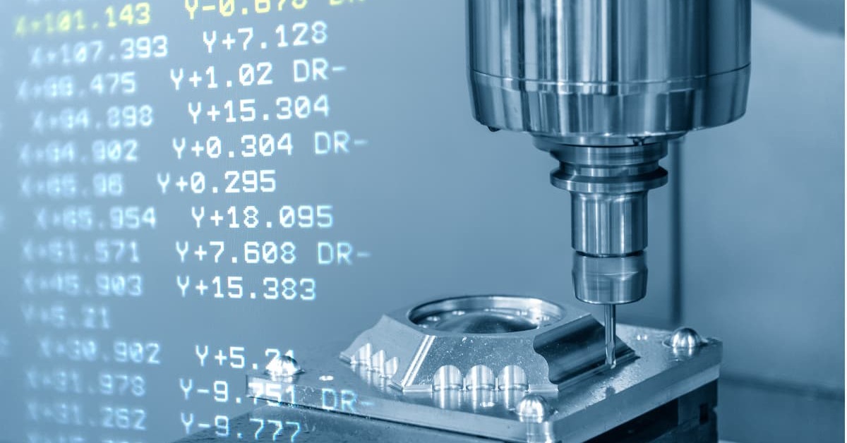
What Is G Code in Machining?
G-code is a CNC programming language that directs a CNC machine’s functions related to the cutting tool’s movement. It stands for ‘Geometric code.’ G-code guides the CNC machine’s actions by combining instructions readable by the microcontroller. This simple programming language requires no intricate logic or mathematical skills.
Using Cartesian coordinate systems, G-code instructs the CNC machine tool on the workpiece’s actions and location. Each command begins with an alphanumeric code, starting with G or M, enabling operators to automate the machining process and ensure precise cuts.
Beyond basic commands like “move here” or “cut this,” G-codes encompass subprograms, subroutines, and machine-specific instructions. For instance, lathe G-codes control spindle functions, while milling machines specify tool details for each operation. 3D printers have their commands, such as heating the extruder.
Individual G-code programming languages are available online as open-source. Two types of G-codes exist in CNC precision machining:
- modal: remains effective until changed
- non-modal: operates only within the block where used.
Role of G Codes in CNC Machines
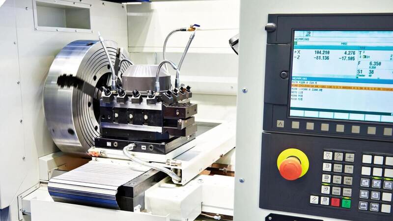
G-codes are essential in CNC programming, serving a crucial role in the automation of CNC (Computer Numerical Control) machining. CNC machines rely on these codes as they cannot understand conversational languages, operating solely on a dedicated set of machine language commands. Programmers compile these commands into a G-code file to provide instructions on how CNC machines should function.

The CNC programming microcontroller is preprogrammed to understand the meaning of each G-code command. Consequently, when the microcontroller reads a specific command, it immediately knows how to execute it. If any G-code command falls outside the microcontroller’s dictionary, it will not function.
G-codes work to control CNC machine tool movements, while M-codes oversee various functioning processes like coolant flow or tool change. The combination of M-code and G-code commands forms a complete CNC programming file.
Common G-code Commands Used in CNC Machine
The CNC programming process involves over a hundred G-codes, making it challenging to memorize each code and its meaning. Memorizing essential commands like G00-G03 is beneficial, as they feature prominently in every CNC programming project.
Here is a list of commonly used G code commands in CNC programming, serving as a reference when creating CNC programming files.
CNC Machine Movement and Travel
The following codes control movement and tool path in CNC programming:
G00: Rapid Movement of Machine Tool
Rapid movement swiftly transports the tool between points without cutting material. Movements occur at the highest speed, requiring no specified feed rate. Location coordinates in the X, Y, and Z axes are necessary.
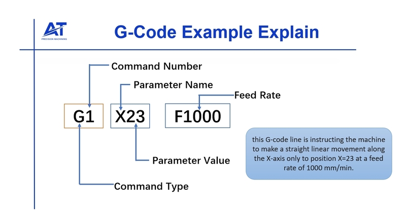
G01: Linear Interpolation of Machine Tool
Linear interpolation guides the tool along a straight line from one point to another, with speed determined by the specified feed rate (‘F’ in the G01 command block).
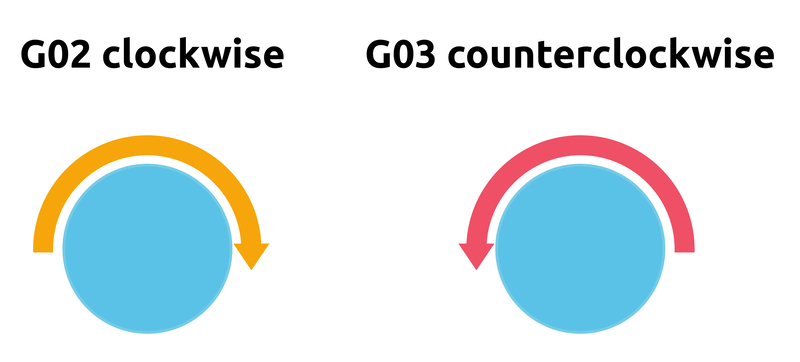
G02: Clockwise Arc Circular Interpolation
G02 commands the cutting tool to follow an arc in a clockwise direction instead of a straight line. A specified feed rate (‘F’) is required, along with details about the arc center point (I, J, K) or radius (R).
G03: Counter Clockwise Arc Circular Interpolation
Like G02, G03 cuts an arc in the counterclockwise direction instead of clockwise.
G04: Dwell
Dwell introduces a pause in the program, halting machine movements while auxiliary functions continue. For example, the spindle keeps moving during Dwell. The pause duration is indicated by the ‘P’ value, read in seconds.
G09: Exact Stop
The exact stop G-code is used when a sharp corner is needed, addressing the issue of rounded corners caused by cutting tool inertia. G09 stops the cutting tool momentarily at the corner and then resumes, ensuring sharp corners.
Machining Plane Selection
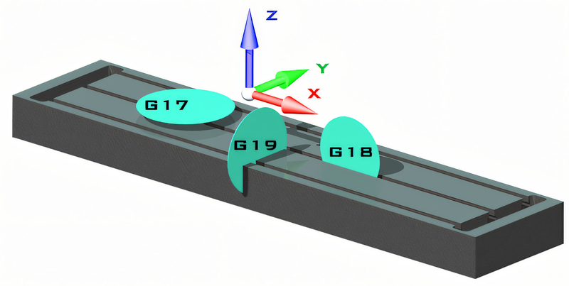
G-code programs for plane selection specify the two-dimensional plane in the X, Y, Z-axis Cartesian coordinate system. The G code commands for this purpose are:
- G17: XY Plane Selection
- G18: XZ Plane Selection
- G19: YZ Plane Selection
Machining Dimensions
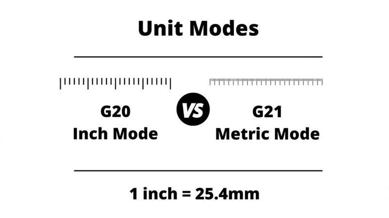
The G-code program for dimensions specifies the chosen measurement units. The commands for this purpose are:
- G20: Change unit measurement to inches
- G21: Change unit measurement to millimeters
Compensation Codes
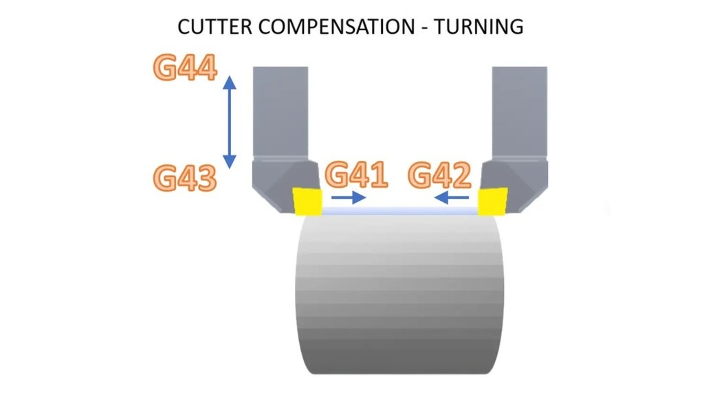
Cutter compensation permits the CNC controller to account for the cutting tool’s size. Activating cutter compensation instructs the machine to adjust the cutting tool radius to the left with G41 or to the right with G42. You can use the same program with various cutting tools by specifying the cutting tool’s diameter. G40 deactivates the cutter compensation modes G41 or G42. These commands are:
- G40 – Turn off tool compensation
- G41 – Cutter compensation left
- G42 – Cutter compensation right
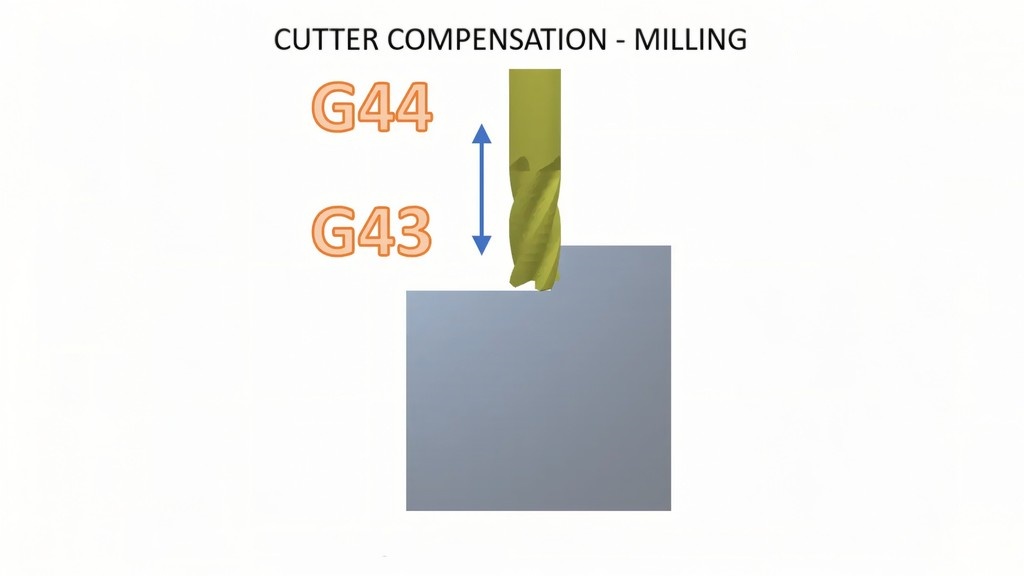
- G43 – Tool length compensation
- G40 – Cancel tool length compensation
The G43 command activates tool length compensation in the CNC machine, while the H code (height) specifies the compensation amount. During setup, H offset numbers, representing the tool’s length, are entered and stored in the machine’s memory. These values are associated with a location known as the offset table or library. The tool table can store multiple H offsets, each linked to a corresponding H offset value.
Cancel Codes
G50 is used for scaling off. In some machines, it may program the absolute zero center point or set the spindle speed limit. G80 is the command to cancel all active canned cycles.
Work Offsets
Work offset ensures the workpiece is at the true zero position. The G code commands for work offset values are:
- G54 – Work Offset 1
- G55 – Work Offset 2
- G56 – Work Offset 3
- G57 – Work Offset 4
- G58 – Work Offset 5
- G59 – Work Offset 6
The G54 command informs the CNC machine about your part’s location, establishing the current work offset zero used in the CNC program. When the G54 work offset code is chosen, all dimensions and regions in the program become relative to the new zero location of the part. A CNC can have multiple work offsets, each relative to the machine’s zero location. This G code is modal, staying in effect until canceled. Think of work offsets as presets on your radio, where you store a location instead of a radio frequency.
Canned Cycles
The provided G-codes are default mini-programs designed to expedite the programming process, allowing programmers to incorporate them into various program parts related to drilling, tapping, boring, and reaming along the Z-axis.
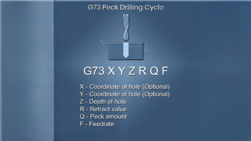
- G73: High-Speed Peck Drilling – Peck drills a hole by drilling and retracting repeatedly, preventing long chips that might wrap around the drill bit.
- G74: Left-Hand Tapping – A tapping cycle for left-hand threads with a counter-clockwise spindle rotation.
- G76: Fine Boring Canned Cycle – Bores a hole, stops the spindle, moves the tool away to prevent marking, and rapidly retracts the tool.
- G80: Canned Cycle Cancel – Cancels active canned cycles for drilling, boring, tapping, and reaming.
- G81: Standard Drilling Cycle – Allows the machine to drill the hole in one straight shot and then rapidly retract the drill bit.
- G82: Standard Drill Cycle with Dwell – Drills a hole without pausing, dwells at the bottom for a specific time, and rapidly retracts, used for better surface finish.
- G83: Deep Hole Peck Drilling Cycle – Drills in pecks, retracting entirely from the hole between each peck to clear chips, suitable for blind holes.
- G84: Right-Hand Tapping Cycle – Standard tapping cycle with clockwise spindle rotation.
- G85: Reaming Cycle – Feeds to the bottom of the hole and rapidly retracts, similar to the standard drilling cycle.
- G86: Boring Cycle – Feeds to the bottom of the hole and rapidly retracts without pulling the tool away.
- G87: Back Boring Cycle – Bores a hole from bottom to top, the reverse direction of G86.
- G88: Boring Cycle with Dwell – Bores a hole and dwells at the bottom for a specified time.
- G89: Back Boring Cycle with Dwell – Feeds to the hole’s bottom, pauses, and rapids out without pulling the tool away first.
Positioning Modes

The positioning mode determines how the CNC machine reads position commands. The G-code programs for different positioning modes are:
G90: Absolute Mode Positioning
G90 sets the CNC to absolute positioning mode, interpreting location values relative to a single zero location, usually the workpiece or machine zero.
G91: Relative Positioning
G91 sets the CNC to incremental positioning mode, interpreting location values relative to the machine’s current position. It is useful for repetitive tasks like drilling multiple holes and cancels absolute positioning when specified.
Speeds and Feeds
The speed and feed modes dictate how the machine interprets value units. The commands include:
- G94: Feed per Minute Mode – G94 sets the feed rate to units (inches/mm) per minute, causing the tool to move at a predetermined rate.
- G95: Feed per Revolution Mode – G95 establishes the feed rate in units (mm/inches) per revolution, meaning the tool moves at a specified rate for each spindle rotation.
- G96: Constant Surface Speed – The spindle speed adjusts to maintain a consistent surface speed of the CNC machining material.
- G97: Constant Spindle Speed – The spindle operates at a constant RPM.
Plane Return
Commands for plane return consider the cutting tool’s location in different planes. Common plane return commands include:
- G98 – Return to Initial Plane
- G99 – Return to Rapid Plane
| G-Code words | |||
|---|---|---|---|
| GO | Rapid Linear Motion | G59.2 | Select Coordinate System 8 |
| G1 | Linear Motion at Feed Rate | G59.3 | Select Coordinate System 9 |
| G2 | Arc at Feed Rate | GSO | Cancel Modal Motion |
| G3 | Arc at Feed Rate | G81 | Canned Cycles – drilling |
| G4 | Dwell | G82 | Canned Cycles – drillinq with dwell |
| G10 | Set Coordinate System Data | G83 | Canned Cycles – peck drilling |
| G17 | X-Y Plane Selection | G85 | Canned Cycles – borinq,no dwel I, feed o ut |
| G18 | Z-X Plane Selection | G86 | Canned Cycles – boring, spindle stop, rapid out |
| G19 | Y-Z Plane Se lection | G88 | Canned Cycles – borinq, spindle stop, manual out |
| G20 | Length Unit inches | G89 | Canned Cycles – boring, dwell, f eed out |
| G21 | Lenqth Unit milimeters | G90 | Set Distance Mode Abs olute |
| G28 | Return to Home | G91 | Set Distance Mode Incremental |
| G30 | Return to Home | G92 | Coordinate System Offsets |
| G53 | Move in Abs olut Coordinates | G92.1 | Coordinate System Offsets |
| G54 | Select Coordinate System 1 | G92.2 | Coordinate System Offsets |
| G55 | Select Coordinate System 2 | G92.3 | Coordinate System Offsets |
| G56 | Select Coordinate System 3 | G93 | Set Feed Rate Mode units/minutes |
| G57 | Select Coordinate System 4 | G94 | Set Feed Rate Mode inverse time |
| G58 | Select Coordinate System 5 | G98 | Set Canned Cycle Return Leve I |
| G59 | Select Coordinate System 6 | G99 | Set Canned Cycle Return Leve I |
| G59.1 | Select Coordinate System 7 | ||
Conclusion
It’s crucial to grasp G code to understand CNC programming and produce parts through automated machining. The good news is that understanding how to read G-code is a quick process. Numerous G-codes exist for different instructions. The list above can serve as your reference point for using G-codes in CNC programming endeavors.
Note that G-codes might vary slightly depending on the specific manufacturing model in use. Hence, referring to the machine’s user manual is advisable. This will help you identify any distinctions in your equipment’s CNC programming design.

However, it is always best to work with a reliable manufacturing company to get the best results for your project. Therefore, leave your machining projects with the experts at AT-Machining. We are always ready to bring your design to life with expert CNC programming and CNC machining capabilities.
FAQs
Do All CNC Machines Use the G Code?
Certainly, all CNC machines operate using G-code. The integration of G-code is inherent in every type of CNC machine’s microcontroller. Nevertheless, manufacturers occasionally tweak the G-code format slightly to suit their specific machines.
For example, variations might exist. For example, the addition of a ‘0’ before the numerical values of the G-code. While one machine represents rapid movement G-code as G00, another might use G0.
How Many G Codes Are Available for CNC Machines?
Numerous G-code commands are used in CNC programming, with many being universal across various operations. However, specific G-codes are tailored to distinct operations like milling, turning, or drilling.
It’s important to note that the G-code list can vary among different CNC manufacturers. Not every machine supports every G-code. Those with unique features or multi-axis capabilities might incorporate additional G-codes. Manufacturers typically provide guidance on CNC programming G-codes in the reference manual accompanying the CNC machine.
Are there Safety Concerns for Programming G-codes?
There are safety considerations to bear in mind when programming G-code for a CNC machine. Improper G-code poses potential safety risks for the machine, the operator, and the work area.
Ensuring accurate work offsets and tool length offsets in the G-code is crucial to prevent tool breakage, a common occurrence resulting from tool collisions. Running simulations in CAD and CAM software beforehand helps eliminate errors and bugs in the G-code, further enhancing safety.
What Other Code Is Used in CNC Machining?
M-code is another crucial element in CNC programming. M-codes specifically govern various functions of the CNC machine that are unrelated to movement. These m-code commands are tailored to the specific CNC machine controller and its supported features. In CNC programming, M-codes and G-codes work together to achieve comprehensive control over the machine.