Skip to content
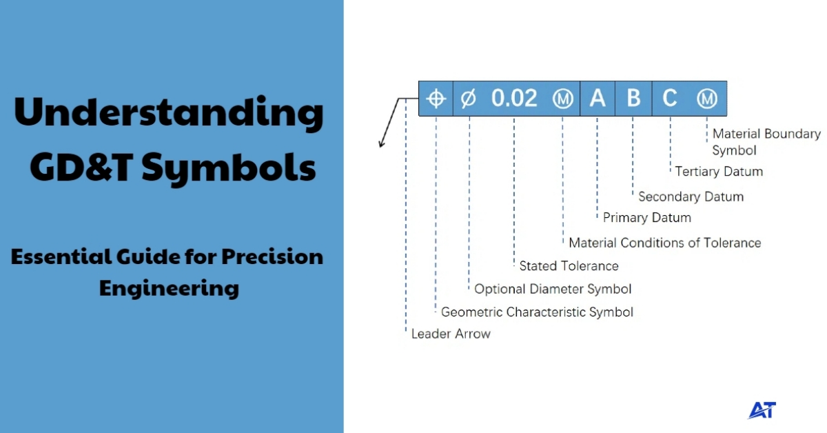
What is GD&T?
Geometric Dimensioning and Tolerancing (GD&T) is a symbolic language used on engineering drawings to define the shape, size, orientation, and location of features on a part. GD&T provides a more precise method of conveying the designer’s intent, as well as the functional aspect of the part. It also provides geometric tolerances that define the acceptable amount of variation allowed in a part feature.
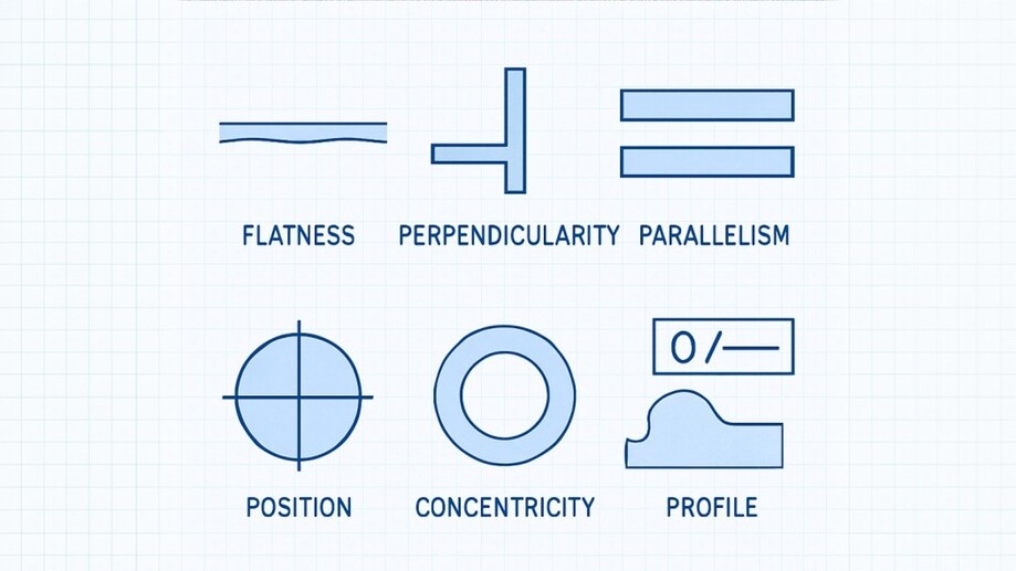
Tolerances include things like flatness, straightness, circularity, parallelism, and line profile, which essentially apply to the feature, relative to one another, so parts fit together and work, in real-world conditions, despite slight variations in, for example, manufacturing.
A major benefit of GD&T and GD&T symbols is that they consider processes of manufacturing, allowable variation – for example, a hole may be roundish rather than a perfectly circular feature, but as long as it is within the tolerance zone specifying roundness, we could still utilize it in the final assembly.
The Role of GD&T Symbols
GD&T revolves around its symbols as a common language for engineers and manufacturers. The symbols take complex instructions and express geometric needs in a more compact, visual format that conveys meaning. Rather than hand-writing long notes on engineering drawings, a simple symbol can convey the need for a surface to be flat, or to control concentricity, or for two features to remain parallel.
As a result, GD&T symbols help ensure design intent will always remain intact during manufacturing. For example, the designer may design a shaft to remain straight within a tolerance so it can rotate smoothly inside a bearing. Without GD&T symbols, vague dimensional notes would need to express the need for the shaft to be straight.
The symbols also describe the tolerance zone, or the three-dimensional zone of the part, in which a feature must reside. A feature control frame uses symbols to not only define the type of control being exercised on the entire feature, but also tells the designer, or someone measuring the part, what the datum reference frame is that will be used as a coordinate system for the measurements.
In this way, nothing is vague. A part can be measured with confidence using common modern tools available for inspection and measuring, such as coordinate measuring machines (CMMs).
In the end, GD&T symbols translate engineering drawings into the manufacturing world. They assist in minimizing mistakes, reducing costs, and improving quality control by ensuring that everyone, from the designer to the machinist, is interpreting the requirement in the same manner.
Key Elements of GD&T
GD&T is based on several key elements that outline the use and interpretation of dimensional tolerances. These feature surface elements provide clarity in engineering drawings and consistency across design, manufacturing, and inspection:
Feature Control Frame
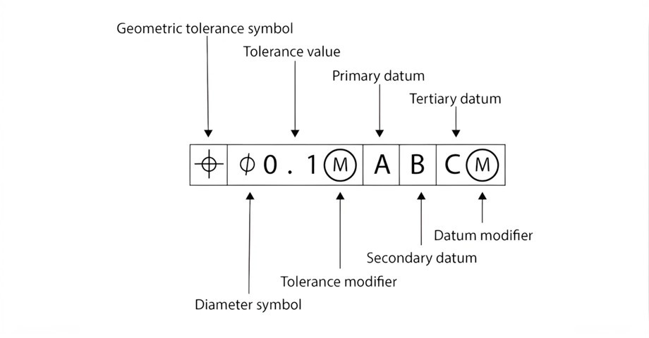
The feature control frame is the basis of GD&T. It identifies what geometric control applies to a feature, the tolerance zone for acceptable variation, and the datum reference frame for measurement. A typical control frame includes the geometric symbol, the tolerance value, and any datum features.
Together, a feature control frame communicates unambiguous requirements in a form that everyone–designers, machinists, and inspectors–understands universally.
Datums Feature
Datums are imaginary points, lines, or planes and provide a frame of reference for measurements. Together, they define a datum reference frame, which is like a coordinate system for the part. Usually, the primary datum is the most important surface, the secondary datum establishes alignment, and the tertiary datum locks in the last degree of freedom to define a measurement direction.
This consistent structure ensures individual features and other measurements are specified relative to a consistent and repeatable reference, and this is key to parts requiring fit and function together.
Material Condition
Material condition indicates the manner in which tolerances apply for a feature based on the amount of material. At maximum material condition, the feature has the maximum material, represented by the largest possible shaft in the feature or the smallest hole allowed.
The least material condition is representative of the least material possible; in the case of a feature, it could be the smallest shaft or the maximum hole. These conditions matter in determining how much additional tolerance (commonly called bonus tolerance) is available during production and measurement, and can help engineers develop a good balance between design intent and manufacturing flexibility.
Tolerance Zones
A tolerance zone represents the 3-dimensional material boundary, within which the feature must reside. Depending on the geometric control, this zone could be comprised of two parallel planes, a cylindrical feature surface, or a projected tolerance zone extending into space.
For instance, straightness could have a narrow tolerance zone based on the centerline, and parallelism would need to have two perfect planes. The tolerance zone concept guarantees that even if the features do not fulfill perfection, they can still perform within the tolerance described for said feature.
How GD&T Symbols Apply in Engineering
Accuracy and consistency are essential in CNC machining. GD&T supplies the structure to guarantee that every part created fulfills the design’s functional specification, regardless of how complicated the geometry is. GD&T defines the permissible variation of features and enables you to express design intent to a manufacturing process without ambiguity.
For machinists, GD&T inhibits the guesswork by explicitly expressing how features are to relate to one another. For example, a hole that is defined with true position not only tells the CNC programmer where the hole is to be located, but it also states the range of variation for the part to properly assemble. A definition of this type is especially critical in industries that create parts with high precision, such as aerospace, automotive, and medical devices, wherein a small variation can seriously damage the performance of the part.
GD&T is also heavily used in machining shops as part of their QC inspection processes. For example, coordinate measuring machines (CMMs) will take the datum reference frame and tolerance zones specified in the engineering drawing, and utilize this information to measure and check the part for conformance. The direct connection between part design and inspection helps reduce rework, lower production costs, and ensure the desired functioning of parts.
By employing GD&T practices, CNC machine shops can ensure part compatibility with other mating parts, achieve tighter tolerances, and maintain process efficiency when working with complex part geometry.
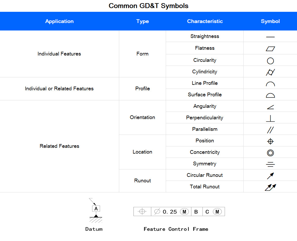
Common GD&T Symbols
Modifiers and Tolerance Zones
GD&T Modifiers
| Modifier | Symbol | Description | CNC Machining Example |
|---|---|---|---|
| Maximum Material Condition (MMC) | Ⓜ | Applies when a feature contains the most material (the largest shaft, smallest hole). Allows bonus tolerance. | A turned shaft at max diameter must still fit into its mating hole; smaller diameters gain extra tolerance. |
| Least Material Condition (LMC) | Ⓛ | Applies when a feature contains the least material (smallest shaft, largest hole). | A thin CNC pocket wall must not go thinner than allowed, ensuring strength. |
| Regardless of Feature Size (RFS) | Ⓡ or implied (default) | Tolerance always applies regardless of size. | A drilled hole must meet positional tolerance, whether it’s large or small, within its limits. |
| Continuous Feature | Ⓒ | Treats multiple surfaces or features as one. | A CNC slot across two faces must be measured as one continuous slot. |
| Free State | Ⓕ | Applies to parts that flex when unrestrained. | A thin CNC bracket measured without clamping force. |
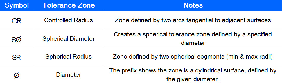
GD&T Tolerance Zones
Benefits of GD&T Symbols in Precision Engineering
Below are several benefits of GD&T in precision engineering:
Enhanced Clarity in Engineering Drawings
One of GD&T’s greatest advantages is the ability to reduce ambiguity in communication. Traditional dimensions can easily promote subjective interpretation, as a drawing specification may mean something different to various individuals, especially when parts are characterized by irregular shapes or multiple datums.
GD&T utilizes a standardized set of symbols that everyone understands; engineers, machinists, and inspectors all interpret the same message. This minimizes errors, reduces setup time, and ensures that the design intent remains intact from the concept to the completed part.
Reduced Manufacturing Costs
GD&T helps manufacturers avoid unnecessary precision that raises manufacturing costs. Instead of over-dimensioning dimensions on every feature, the engineer can specify tolerances only where it is functionally necessary.
For instance, the location of a hole pattern may be critical, but the outer surface of a non-mating feature can incorporate much more latitude in tolerance. By directing machining effort only where it is necessary, CNC shops can lessen operation time, decrease wear on tools, and realize material efficiencies while maintaining the design intent and quality levels.
Improved Quality Control
In today’s fabrication environments, quality is paramount. GD&T defines precise tolerance zones that can be verified using the latest inspection tools, such as coordinate measuring machines (CMMs).
This enables the inspector to verify whether a part complies with design intent promptly, in addition to preventing guesswork, by adopting standard inspection procedures. The use of GD&T decreases the probability of inspector error, increases repeatability, and lends itself toward a successful audit.
Guarantees Part Interchangeability
Precision engineering often includes interchangeability requirements for parts. This is particularly common for situations in the aerospace, medical, and automotive industries. GD&T ensures that mating parts will fit and perform together, regardless of whether the parts were created on different machines, by different suppliers, and at different times.
Determining the perfect form, orientation, and location characteristics offered by GD&T ensures that parts will mate together, providing a seamless transition from initial proof of principle to production, and increasing production without issues during assembly.
Supports Statistical Process Control (SPC)
GD&T works harmoniously with statistical tolerance process control methods and quality management systems. Manufacturers can identify process variation early and correct it before any parts fall out of tolerance, while monitoring critical features within established tolerance zones. This proactive approach minimizes scrap, saves time and materials, and supports continuous improvement efforts in CNC machining activities.
Conclusion

Geometric Dimensioning and Tolerancing is more than symbols on an engineering design. It is the basis of an accurate manufacturing process. By outlining what variation is allowed, defining datums, and establishing tolerance zones, GD&T symbols helps eliminate uncertainty, ascertain consistent quality, and control manufacturing costs. In CNC machining, where accuracy and repeatability rely on precision processing, GD&T is the difference between parts that fit and parts that function reliably, no matter the conditions.
At AT Machining, these principles are implemented every day to manufacture CNC parts that hold tight tolerances, have good surface finishes, and function in a repeatable manner. This experience assures that, whether prototyping or manufacturing to specifications, AT Machining will produce every part to match the design intent while managing costs. Contact us today to get started!