Skip to content
Overview of Machining Allowance
Machining allowance refers to the planned or intentional extra material left on a workpiece to accommodate subsequent finishing operations. Machining allowance, also known as machining margin or stock allowance, is a strategic design requirement that supports functional engineering fits desired in mechanical assemblies.
Allowances are specified in two major forms, including total allowance and process allowance. Total machining allowance includes material left on the entire chain from raw stock to finished product, whereas the process machining allowance refers to the material left for one specific operation
Engineers and designers of mechanical parts often define a specific allowance between components of a shaft and hub assembly to achieve an engineering fit. Incorporating extra material provides a safety margin in engineering, accounting for overlaps and gaps to ensure mating components have the right fit.
Why Is Machining Allowance Important in Precision Manufacturing?
Machining allowance is one of the common engineering practices in contemporary manufacturing for several reasons, including:
- Supports Assembly: Using the appropriate allowance in machining ensures mating parts fit together perfectly to minimize errors and the need for rework. Accurate allowances help electronics components connect easily and securely.
- Improves Process Reliability: Specifying allowance in precision machining offers a safety margin for unplanned deviations in the early stages of machining. Thus, it ensures quality control and minimizes the risk of rework and scrap.
- Account for Warping or Distortion: Having an allowance provides machinists with extra stock to rectify machining defects such as distortion or warping, which occur during welding, heat treatment, or rough machining.
- Dimensional Accuracy: Leaving extra materials on the workpiece surface provides a safety margin for machinists to perform finishing operations. Thus, they can leverage cutting parameters such as low depths of cut and high speeds to ensure the dimensions of final parts align with the necessary specifications.
- Surface Finish: Engineers incorporate allowances in design to account for the stock removal in post-machining procedures like grinding or polishing. Machinists can manage the surface imperfections of machined parts during finishing passes to ensure the final product meets the design parameters. Consequently, it ensures a consistent and uniform surface finish without sacrificing the overall dimensions of the machined component.
Machining Allowance and Engineering Fits
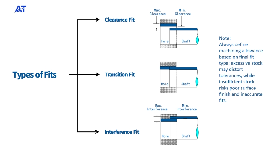
Allowances are practical design features that allow the desired fit between mating parts for peak performance and proper functioning. Engineers define specific machining allowance on the design of a part based on the desired type of engineering fit. We’ll consider the three major types of fits below:
- Clearance Fit: It includes a positive allowance, which indicates the presence of a gap between the mating parts. For instance, machinists may use a machining allowance of +0.2 mm for a shaft with an outer diameter of 39.8 mm and a hole with a 40.0 mm diameter. Clearance fits allow both the shaft and the hub to slide or rotate freely in an assembly.
- Interference Fit: A negative allowance that shows overlapping of mating parts. For instance, the allowance is –0.2 mm if a shaft has a diameter of 62.1 mm and the hole maintains a 61.9 mm diameter. Design engineers often employ this type of fit in permanent high-strength connections, like in a hub-shaft system.
- Transition Fit: This type of engineering fit combines the attributes of the clearance fit and interference fit. For example, if the shaft diameter is 40.0 mm with a tolerance of – 0.05 mm and the hole diameter is 40.0 mm with a + 0.05 mm tolerance, the fit will typically vary between a slight interference and a slight clearance. It is typically used in positioning bearing housings.
Overview of Tolerance

Tolerance is the measure of the unplanned deviation in the machined part dimension. It is imperative to note that even the most precise CNC machines can’t offer perfect accuracy due to unavoidable challenges or potential inaccuracies that may arise in manufacturing operations. Machining tolerance measures both upper and lower limitations on the degree of deviation a dimension may experience from its true value or exact size.
Different Tolerancing Strategies Used in Technical Drawings
Product engineers adopt different tolerancing strategies in engineering drawings to foster clear communication and ensure accurate manufacturing. They include:
Direct Limits
Direct limit tolerances indicate the maximum and minimum permissible sizes for a dimension. It is a standard tolerance strategy due to its clarity and space-saving benefits. Nevertheless, direct limits don’t show the base dimensions, which can be challenging when you need precise information. For instance, if a dimension is specified with direct limits as 30.0 – 30.2 mm, the component must maintain this range. Its final diameter must neither be smaller than 30.0 mm nor exceed 30.2 mm.
Plus and Minus Tolerances
Plus and minus tolerances specify the allowable deviations from a base value. Although this strategy offers detailed information for a design, it can make a drawing cluttered. This tolerancing approach often includes:
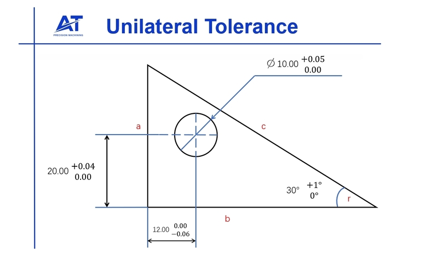
- Unilateral Tolerances: Indicates deviation on only one side of the base dimension (either negative or positive). i.e., if a dimension is specified as 12.0 mm with a tolerance of +0.06 mm / -0 mm, the component can be up to 20.06 mm but not smaller than 20.0 mm.
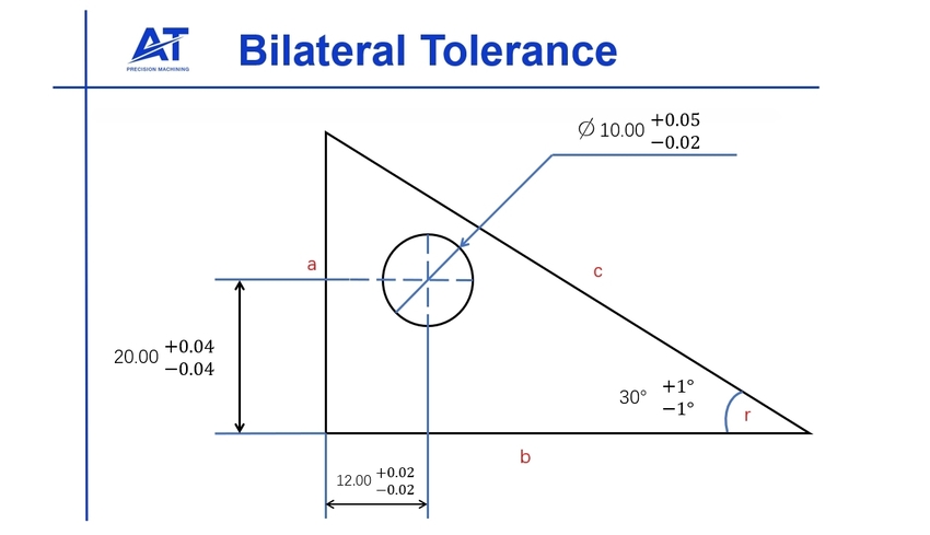
- Bilateral Tolerances: Indicates deviation on both sides of the base value. Bilateral tolerances show both negative and positive variations. i.e., if a dimension is specified as 12.0 mm with a tolerance of ±0.02 mm, the part must fall within the range of 19.98 mm to 20.02 mm.
How Do You Calculate Machining Allowance?

Defining machining allowance in engineering drawing is a practice best left for professionals. The practice of leaving the appropriate machining allowance for parts is more experience-driven. Moreover, product engineers and technicians often consider several factors to determine the appropriate machining allowance for a component. We’ll consider some of these factors below:
Material Properties
In CNC machining, materials with higher ductility typically require more stock. This may seem counterintuitive, as ductility (such as aluminum, copper, and mild steel) implies that the material is “soft” and easily deformed. However, these very characteristics lead to a series of complex issues during cutting, necessitating greater stock allowance to ensure final dimensional accuracy and surface quality. Take copper, aluminum and stainless steel as an example
| Material | Key Machining Challenges | Typical Allowance (Single Side) | Primary Purpose of Allowance |
|---|---|---|---|
| Copper | Very soft, “gummy,” severe BUE, spring-back. | Most (1.0 – 2.5 mm) | To compensate for clamping deformation, cutting instability, and elastic spring-back. |
| Aluminum | Soft, high thermal expansion, spring-back. | Large (1.0 – 2.0 mm) | To compensate for clamping deformation, spring-back, and thermal expansion. |
| 304 Stainless | Severe work hardening, high toughness, poor thermal conductivity. | Least (0.5 – 1.0 mm) | To ensure the finishing tool cuts under the work-hardened layer left by the roughing pass. |
Manufacturing Process
The technique used to produce the part before machining provides detailed information on its roughness is a key factor in calculating allowance in machining. Take casting and forging, for example, cast parts generally require a larger machining allowance between 2 – 5 mm since they are commonly less dimensionally accurate. Forged parts, on the other hand, may require 1 – 3mm machining tolerances because they are typically near-shape.
Machining Type
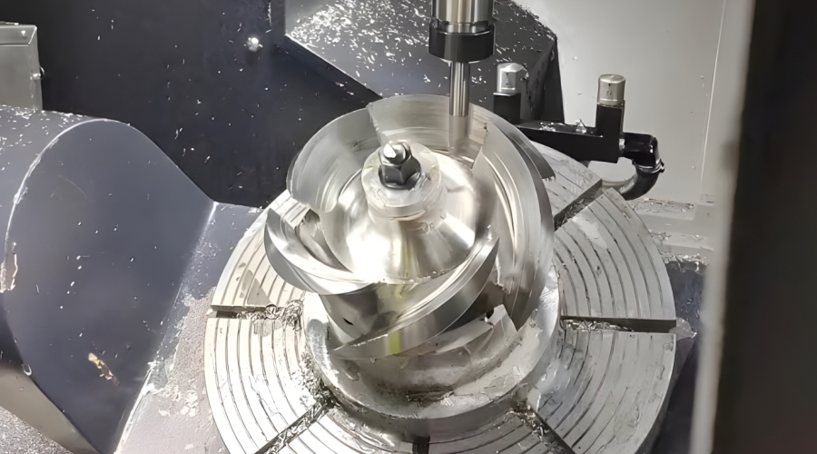
Finishing processes with final cuts and less material removal require a smaller machining allowance than roughing operations involving bulk material. For instance, the initial rough turning cuts on the workpiece blank in a turbine blade machining operation require high machining allowances (3 – 4 mm). Machinists use smaller machining allowances (0.5 – 1mm) for semi-finishing and finishing cuts as the process progresses and the profile of the blade takes shape.
Finish/Tolerance
Product designers often make drawings of components with high-quality requirements, like fine surface finish and tight tolerance, with more machining allowances to ensure that minor deviations can be rectified during the final passes.
In the absence of a fixed formula for determining machining allowance, engineers use a general guideline to account for its main factors. It is represented as:
Surface variation + Tool Access Margin + Finish Requirement Buffer = Machining Allowance
How Does Machining Allowance Compare to Tolerance in Precision Manufacturing?
Allowances and tolerances are fundamental concepts in accounting for dimensional variation. While they are often confused, their purposes and applications differ in engineering. For this reason, it is necessary to distinguish them to achieve accurate engineering design and mitigate production mistakes. We will take a closer look at machining tolerance and allowance to identify how they differ below:
Allowance is the planned deviation in mating parts’ dimensions. In other words, it is the extra material an engineer leaves on the workpiece ‘intentionally’ which acts as a leeway adjustment and is usually removed in a controlled environment in future machining operations. It ensures there is sufficient material on the workpiece to achieve the desired fit in mating surfaces.
Machining allowance values account for variables such as manufacturing variations, tool wear, thermal expansion, and material inconsistencies to ensure mating parts fit properly. Also, it ensures the desired surface finish, part tolerances, and precise dimensions in mechanical parts.
In contrast, machining tolerances indicate the acceptable range of dimensional deviations in an engineering drawing. Tolerance relates to the reality that even though CNC machining offers highly accurate parts, it is impossible to achieve a perfect machining where machined components maintain theoretical dimensions. Hence, engineers define specific CNC machining tolerance values to account for inevitable manufacturing variation and to serve as a target range for manufacturers to work with.
Machining tolerance ranges accommodate manufacturing variation, allowing manufacturers to control quality and the acceptable range of the dimensions of a mechanical part.
Impacts of Machining Allowance and Tolerance on Precision Manufacturing
Through clear understanding and strategic application of allowance and tolerance values, engineers can significantly enhance efficiency, quality, and cost effectiveness of precision manufacturing processes. Below are the practical implications of these concepts:
Reducing Production Costs
Incorporating the correct allowances and tolerance levels can reduce the need for high-precision CNC machinery, therefore lowering production costs. This is a significant edge, as it helps balance cost efficiency with the need for precision. Tolerances, when properly defined, help save production cost and time by reducing the need for extremely precise machining processes.
Ensuring Part Interchangeability
Engineers generally find that misunderstanding these principles and missteps in implementing the correct values can result in unaligned components of an assembly, resulting in additional costs and delays.
In the automotive sector, engineers often employ clear allowance and tolerance variation ranges to ensure parts from different manufacturers fit together perfectly to maintain optimal vehicle performance and safety.

Facilitating Efficient Assembly
Well-defined machining allowances and tolerances encourage efficient assembly. Engineering experts improve overall workflow and prevent assembly line bottlenecks with clearly defined minimum and maximum machining allowances. Correct tolerances and allowances, particularly in electronic components, contribute to smooth assembly, reduce rework, and increase production efficiency.
Elevating Product Quality
The quality of a product hinges on how well the tolerances and allowance requirements are understood and applied. Generally, products that maintain precise allowance and tolerance values are more reliable and exhibit fewer defects.
Accurate tolerances and allowances ensure products meet stringent safety standards in medical device manufacturing, ensuring top-quality and reliable products.
Optimizing Performance
Through accurate application of machining tolerance and allowance values, engineers ensure the optimal performance of the final product. Errors in specifying these values can compromise the lifespan and functionality of mechanical products.
Machining allowances are critical in aerospace engineering to accommodate desired assembly fit, while precise tolerances ensure the safety and reliability of critical components.
Key Takeaways
Machining allowances are a proactive design requirement that contributes to error mitigation in manufacturing. Strategic incorporation of allowances in precision machining can help manage internal stress, control over surface quality, achieve the desired fit and assembly requirements, and enhance overall product reliability. More so, this compensation gives room for the rectification of any potential discrepancies or surface defects and ensures adequate gaps and clearances for components to fit together seamlessly in an assembly.
AT Machining is a reliable precision machining expert equipped with an advanced CNC facility and extensive expertise in rapid manufacturing and prototyping services for a range of industries. Whether your custom parts require tight tolerance levels or you need the help of professionals to determine the right allowance for your engineering applications, contact us now! Our certified and experienced team can meet strict industry standards and production requirements!