Skip to content
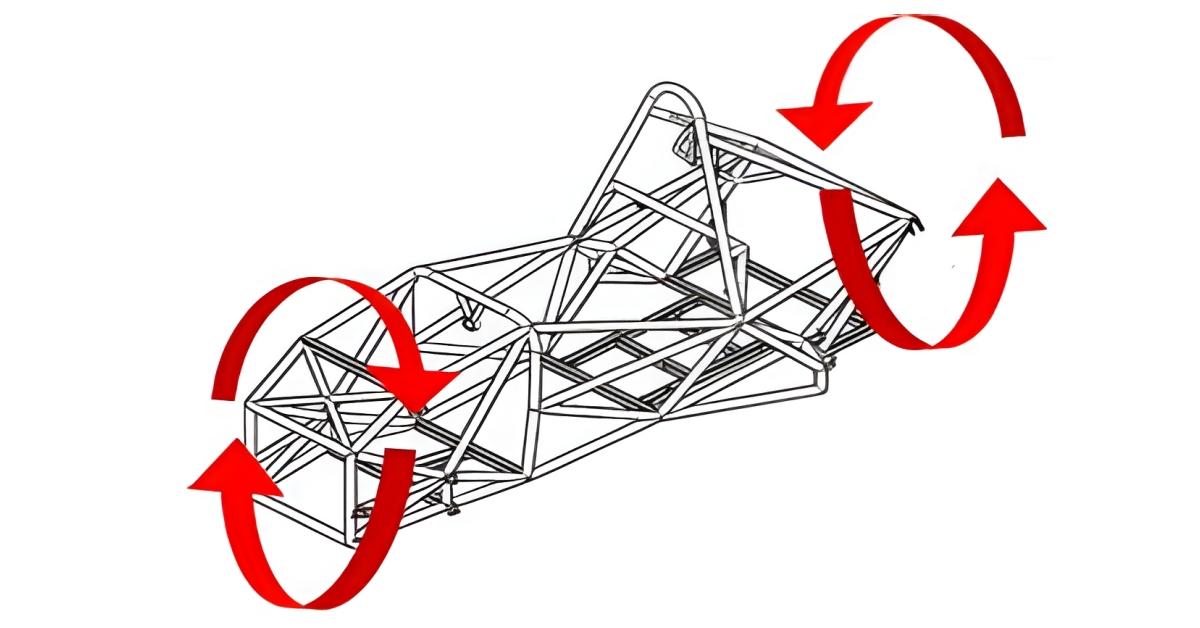
What Does Torsional Stiffness Mean?
Torsion refers to the type of mechanical deformation that an object or structure experiences due to the application of a twisting force or torque. An apt example of torsion may be described as the torque or twisting force that is observed in a driveshaft when you apply the throttle in a race car. The propeller shaft, along with the wheel axles, experiences higher torsional loads.
Torsional stiffness is a fundamental material property that measures the resistance of an object to a twisting force (shear stress) when it acts upon it. That is, it tells how much of a radically applied torque an object or material can withstand before it is damaged or deformed.
Torsional rigidity gauges the torsional resistance of an object to twisting as you apply torque to it and is dependent on its geometry. The torque required to achieve a twist of one unit angular measurement per one unit length of a shaft rises as the torsional rigidity increases.
In reference to the driveshaft example, the shaft’s performance may become unstable when it is twisted too much. For this reason, you might have to choose a shaft with sufficient stiffness to ensure peak and a more stable mechanical interface.
Similar to the propeller shaft, better torsional stiffness in the chassis of a vehicle allows a better ride, optimal performance during handling and efficient suspension. As a result, torsional stiffness is a critical variable in chassis engineering because very high or too low torsional stiffness of the chassis can cause failure.
Furthermore, chassis rigidity is critical in mitigating vibration and maintaining the stability of automobiles, allowing easier control during unexpected events. Peak torsional stiffness of a component is crucial to its life span, particularly those that experience torsional cyclic loading.
Essential Properties and Key Formulas for Calculating Torsional Stiffness
Product designers and engineers often examine specific key properties to enhance the torsional rigidity of a design. Below are some of these properties:
- Shear Modulus (Modulus of Rigidity {G}): Is a gauge of the amount of force needed to deform a material or object. It measures a material’s ratio of stress to strain. A material is considered highly rigid or resistant to twisting force if it requires a higher shear modulus or greater force to deform.
- Polar Moment of Inertia (J): Is a measure of the ability of a material or structure to resist twisting force or torsional loads around its rotational axis.
Torsional Rigidity: G * J
You can also relate torsional Rigidity to torque with the following equation:
Torsional Rigidity = Applied Torque * Length of Shaft Angle of Twist (Radians)
For isotropic materials, you can use the following formula to relate shear modulus (G) to the modulus of elasticity (E) for approximate solutions:
Where
- E (Modulus of Elasticity): represents the rate of normal stress to longitudinal strain; a gauge of the stiffness of the material or object
- V (Poisson’s Ratio): indicates how much a material or object will compress or twist in a perpendicular direction to the direction of the compressive force on it.
Take steel 4340 and aluminum 6061 T6 as examples
Alloy steel 4340 is known for its high strength and toughness. Its typical mechanical properties are:
- Young’s Modulus (E): ~205 GPa (~30×106 psi)
- Poisson’s Ratio (ν): ~0.29
Aluminum 6061-T6 is a widely used general-purpose aluminum alloy, valued for its good strength-to-weight ratio and corrosion resistance. Its typical mechanical properties are:
- Young’s Modulus (E): ~69 GPa (~10×106 psi)
- Poisson’s Ratio (ν): ~0.33
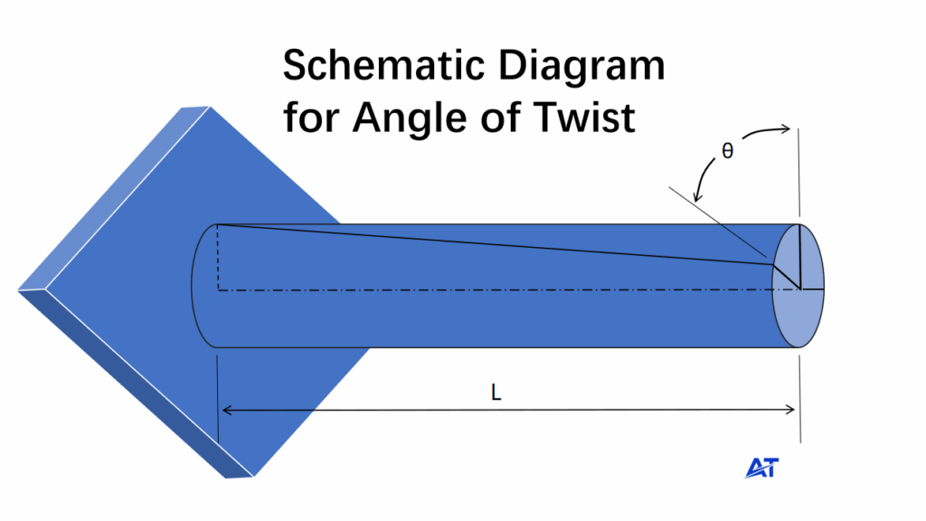
The material properties offer an excellent foundation to predict the torsional rigidity of a component. The following equation will provide the angle of twist (Ɵ) in radians, where the torsional rigidity is represented in JG.
Where:
- T – Torque applied
- L – Length of the material/object
- J – Polar Moment of Inertia (Torsion Formula Constant)
- G – Shear Modulus (Modulus of Rigidity)
The diagram below illustrates the angle of twist in a component:
The polar moment of inertia (J) is the same as the area moment of inertia about the extended axis. As such, the shape of the component will determine the formula for calculating J (Polar Moment of Inertia). Here is the formula for determining J in a cylindrical shaft:
However, it would help to always remember to input the correct value of polar moment of inertia (J) for all calculations because errors can have a significant effect on design decisions.
Torsional stiffness measures the level of twisting force (torque) that can twist one unit length of a component by one unit radian. Below is the formula for solving for torsional stiffness (k):
Applied Examples of the Torsional Stiffness Equation
In this section, we will use an example to explore how to calculate the shear modulus, polar moment of inertia, torsion angle, and stiffness of a component. For ease of analysis, we assume a solid shaft with the following characteristics:
The shaft material is brass (with an elastic modulus of approximately 10e6 psi and a 0.33 Poisson’s ratio). Hence, determining the shear modulus (G) gives:
Solving for the polar moment of inertia for the identified shaft gives:
Calculating the angle of twist (radial torsional deflection) in an object with a torsional load of 5000 in-lb acting on the defined shaft gives:
Optimizing Torsional Stiffness Through Material and Geometry
You can increase the torsional stiffness of a component, such as a shaft, by a factor of four by changing its material from brass to tungsten—one of the hardest and stiffest metals used in CNC machining. Under the same torsional load, the tungsten component will exhibit only one-quarter of the angular deflection or twist of the brass component. Therefore, in any design where high positional accuracy is critical, selecting a material with higher torsional stiffness is essential.
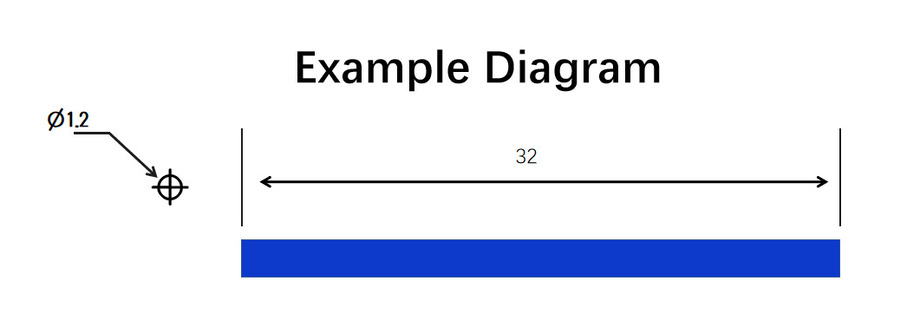
Furthermore, if a material change alone does not provide sufficient stiffness, you can further optimize the design by increasing the polar moment of inertia (J). For instance, increasing a shaft’s diameter from 1.2 inches to 2.0 inches increases its polar moment of inertia (J) from 0.204 in⁴ to 1.571 in⁴. As a result, a 67% increase in diameter boosts the component’s rigidity by a factor of 7.7.
In many cases, component geometries can be complex. Consequently, while the formulas for shear modulus, angle of twist, and stiffness remain applicable, the formula for calculating the polar moment of inertia varies with the part’s geometry. If a standard textbook formula is not available for a given geometry, experts recommend using a CAD system to accurately calculate the polar moment of inertia. You can then substitute the derived ‘J’ value into the relevant equations for further calculation.

How Does Geometry Property Influence Torsional Stiffness
We’ll examine how the geometrical shape of an object contributes to its torsional stiffness in this section:
Circular Cross-Sections
Metal components with cylindrical or circular shapes resist torque at an optimum level due to the even distribution of material from their axis of rotation. Circular sections are often efficient at resisting twisting force because they have a stiffer structure.
Rectangular Cross-Sections
Rectangular cross-sections can also resist twisting, but not as much as circular cross-sectional areas. Cross-sectional area inherently influences the torsion constant in non-circular cross sections such as rectangles, which lack an even distribution of material. Hence, the sides of the rectangular cross-sections do not offer more support to maintain rigidity.
Hollow and Complex Cross-Sections
Hollow sections, such as pipes and tubes, can handle twisting force at high levels since the material’s exterior part resists the force and maintains little weight. This is common in drive shafts, scaffolding, and beams.

Expert Design Guidelines to Improve Torsional Rigidity
Here are some of the essential guidelines to keep in mind to improve the stiffness or rigidity of any component:
- Experts recommend using CAD programs to gather the mechanical properties, like the moment of inertia, for a complex structure.
- You can increase the diameter of a circular shape or a cross-sectional shape (near-circular shape) to achieve a higher torsional stiffness than a material change can provide.
- Ensure to perform a more thorough stress analysis in cases where the torsional load can induce shear stresses that are numerically close to the torsional strength of the material to ensure it doesn’t fail.
- Use materials with a higher shear modulus, like steel, which has an 80 GPa shear modulus, for applications that require higher torsional stiffness.
- Use Young’s modulus for a simple calculation of the difference in torsional rigidity if all other properties remain constant. It may be unnecessary to calculate the modulus of rigidity (shear rigidity) until it is necessary to solve for the angle of twist or stiffness.

Key Takeaways
Torsional stiffness is an inherent property critical for the safety of any material because it helps ensure optimum safety and functionality in components like gears, shafts, or large engineering structures like bridges, ensuring they resist force or withstand load effectively. Having an in-depth understanding of the concept of torsional stiffness allows you to determine the accurate level of torsional stiffness required to ensure adequate performance, efficiency and lifespan.

AT Machining is a top and certified machining service provider with many years of experience in design analysis and material testing. Don’t hesitate to contact us today; our engineering experts can provide groundbreaking solutions and determine the right material with accurate torsional stiffness and rigidity for your project!
FAQS
What Are the Torsional Stiffness Units?
Engineers and designers employ the SI and FPS units of torsional stiffness in structural engineering. The unit of torque is N.m while the unit of the angle of the twist is radian in the SI units system. On the other hand, the unit of the angle of twist is the radian, while the unit of torque is lb.ft in the FPS system.
What Are the Common Applications of Torsional Stiffness?
Product engineers and designers often utilize torsional rigidity or stiffness in engineering components or structures like bridges, skyscrapers, beams, columns, and different machine components, including shafts and gears, that can withstand heavy loads and different forces without failure.