跳到内容
跳到内容 
What Is Engineering Tolerance?
Tolerance in engineering or engineering tolerance is the acceptable variation in a specific measurement from the base measurement or assigned dimensions. Tolerances can apply to different units, including voltage, volume, weight, current, temperature, etc. However, tolerances in engineering apply to angular, linear, and other physical dimensions associated with technical drawing.
No manufacturing method is flawless because every part that has ever been produced has specified engineering tolerances. This tolerance provides a permissible variation in dimension and geometry, which the manufacturer must work closely with.
For instance, if you are to design a sieve to remove 4.5 mm pebbles from 3.5 mm pebbles. It would be best to design it so the smaller pebbles fall through the holes while retaining the larger pieces on the sift. The size of the larger rocks varies between 4.3 mm and 4.7 mm, while the size of the smaller pebbles ranges between 3.3 mm and 3.7 mm.
You can make 3.8 mm the nominal value for the hole diameter to ensure that only the smaller pebbles fall through while the larger ones remain on the sift. However, you can add an upper limit of +0.3 mm and a lower limit of -0 mm to ensure that the holes maintain a tolerance range between 3.8 mm and 4.1 mm.
Types of Tolerances in Engineering
Product manufacturers and engineers use a broad range of mechanical tolerance types in defining the permissible degree of variation in a component’s dimensions. These engineering tolerance types provide accurate insight into the manufacturing requirements and intended functionality. Below are typical types of tolerances in engineering:
Dimension Tolerances
Dimension tolerances refer to the permissible deviation in the size of a component. It is the basis of mechanical engineering. The maximum size is the maximum allowable value, while the minimum value is the minimum dimension.
The absolute value of the algebraic difference between the minimum upper limit size and the maximum upper limit size is called “tolerance.” It is also the absolute value of the algebraic difference between the lower and upper deviations.
Tolerance is usually a numeric value without a minus (-) or plus (+) sign and cannot be a zero (0). How small the dimension tolerance is determines how high the dimension accuracy is within the case of constant basic size. Specified tolerance shows the manufacturing precision requirements and the degree of machining difficulty.
- Nominal Value
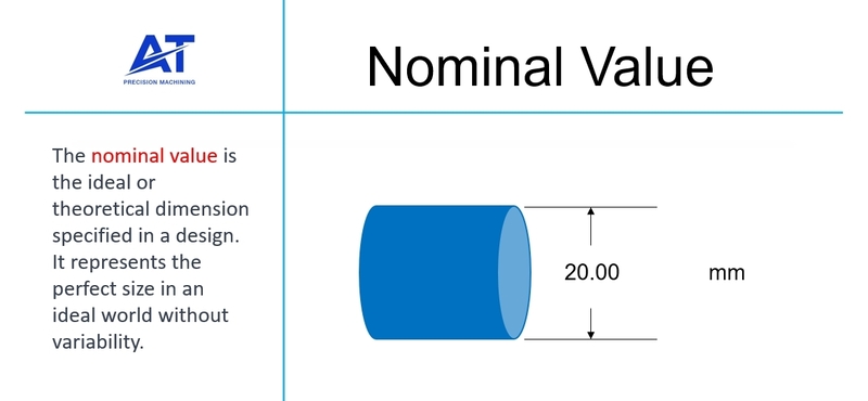
The nominal value is the fundamental dimension often provided on an engineering drawing. Manufacturers must keep to the nominal value if there are no specific tolerances. However, some deviations may occur due to the influence of machining capabilities, machinist competence, machine setup, etc.
- Upper Deviation
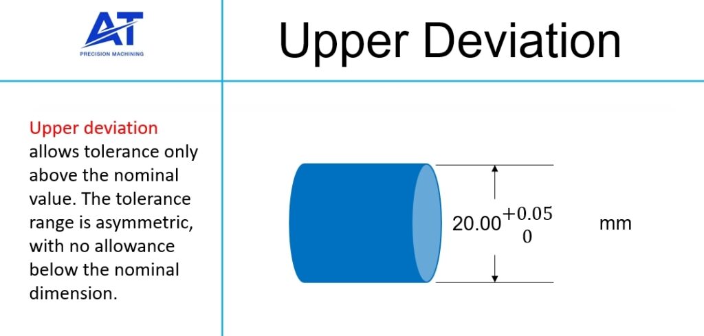
Upper deviation is the direct opposite of lower deviation. When added, it indicates how much larger the measurement for your machined parts can be relative to the nominal value. Thus, the final measurement can range from 100 to 100.5mm based on the tolerance on the drawing.
- Lower Deviation
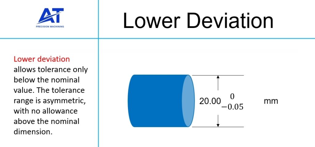
Including a lower deviation in your drawing shows the manufacturer how much smaller the measurement for your parts can be. Besides, this deviation is marked with the “-” sign. A measurement between 99.5 and 100 mm is acceptable. Anything more or less than the said measurement is not within the set limits.
- Bilateral Deviation
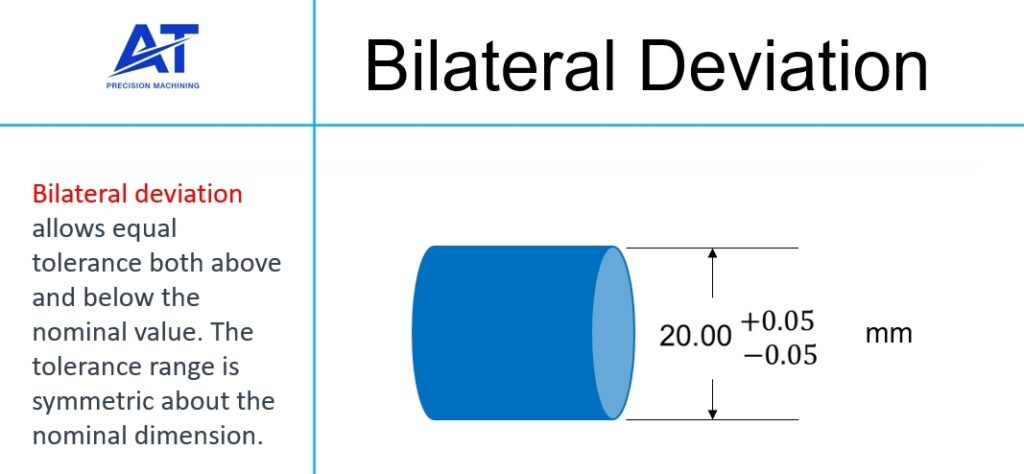
Bilateral deviation is another way to give your product manufacturer a preferred tolerance range. Here, the permissible variation is outlined on both sides of the nominal value. As such, this allows deviation from the nominal value in both negative and positive directions. This type of deviation is ideal when there is no preference for deviation in a specific direction.
For example, the drawing indicates 99.75 as the minimum acceptable dimension and 100.25 mm as the maximum acceptable dimension. Hence, the total permissible deviation or room for error is ±0.5 mm but can deviate by 0.25 mm from the nominal value.
General Tolerances

General tolerances may be included in an engineering drawing as a table or a note (e.g., “ISO 2768-m”) somewhere on the drawing. These tolerances are applicable in different conditions such as chamfer heights, linear dimensions, external radius, angular dimensions, etc.
ISO 2768 is an example of an international tolerance grade commonly used in Europe. ASME’s Y14.5 is the US variant of the same general tolerance standard but doesn’t encompass general tolerances.
However, what is the interpretation of the “ISO2768-m” note on an engineering drawing?
The note informs the manufacturer to use the m (medium) tolerance class when manufacturing the parts. It applies to all dimensions unless the client states otherwise on the drawing. Therefore, a specified tolerance in engineering a hole overrides the general tolerance requirements.
Below is a linear dimension table for further explanation:
| Linear Dimension Range (mm) | Tolerance Class | |||
|---|---|---|---|---|
| F (fine) | M (medium) | C (coarse) | V (very coarse) | |
| 0.5 up to 3 | ±0.05 | ±0.1 | ±0.2 | – |
| over 3 up to 6 | ±0.05 | ±0.1 | ±0.3 | ±0.5 |
| over 6 up to 30 | ±0.1 | ±0.2 | ±0.5 | ±1.0 |
| over 30 up to 120 | ±0.15 | ±0.3 | ±0.8 | ±1.5 |
| over 120 up to 400 | ±0.2 | ±0.5 | ±1.2 | ±2.5 |
| over 400 up to 1000 | ±0.3 | ±0.8 | ±2.0 | ±4.0 |
| over 1000 up to 2000 | ±0.5 | ±1.2 | ±3.0 | ±6.0 |
| over 2000 up to 4000 | – | ±2.0 | ±4.0 | ±8.0 |
As you can see in the table above, the permissible deviation is +/- 0.2 mm if a linear dimension is in the 6 to 30 mm range according to the m (medium) column. Also, +/- 0.8 is the permissible tolerance for dimensions between 400 to 1000 mm. Hence, 25.2 mm is allowed for a 25 mm cut, while 599.2 is permissible following the standard 600 mm nominal value.
GD&T
Geometric dimensioning and tolerancing (GD&T) is a superior and more intricate system that adds another aspect to engineering tolerances basics. It is a universally standardised way of indicating design requirements, even though it is initially daunting and complex.
GD&T describes the geometric tolerances for engineering parts using in-part references. It points out the precise geometric characteristic of the part where the tolerances apply. GD&T goes beyond standard dimensioning and tolerancing (SD&T) by covering geometric characteristics, including concentricity, flatness, and true position.
Fits
Engineered products may sometimes be parts of an assembly that must fit or slip into each other to function. As such, a fit pertains to the dimensional relationships shared by the components of an assembly or the hole with the same basic size and the shaft’s tolerance zone. It determines if the components are tight or loose.
Various options are involved in both the shaft and hole matings, and they often require the appropriate mechanical tolerances to attain the right fit. Other factors, such as ease of assembly, prevailing environmental conditions, and required precision, are fundamental to engineering components for assembly.
Common types of Fits
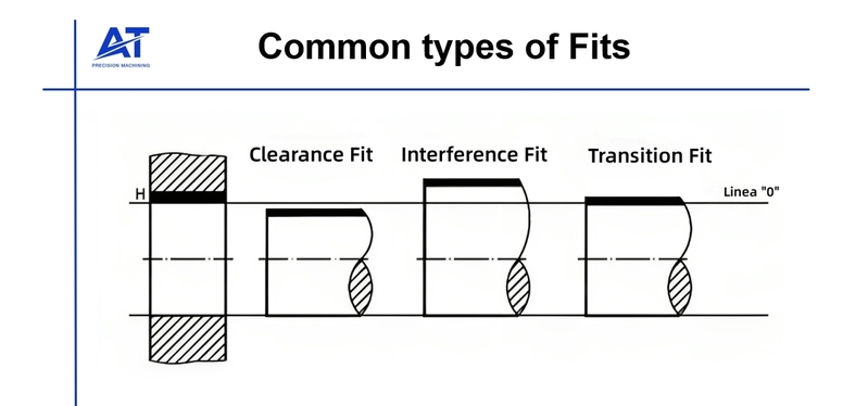
According to ISO, there are different fit types in mechanical engineering. Each fit is suitable for different circumstances. Below are these fit types:
Clearance Fit
A clearance fit is designed for situations that require loose mating and free movement of components. Hence, they are suitable for making products in which components of their assembly must slide in and out easily. Moreover, clearance fits support relative movement between two components joined in an assembly.
The shaft diameter is usually smaller than the hole, resulting in two conditions. One is the minimum clearance in which the diameter of the shaft is higher while the hole has the minimum diameter. Secondly, a maximum clearance in which the hole bears the maximum diameter while the shaft has the minimum diameter.
Interference Fit
Interference fit (also called friction fit or press fit) aids the assembly of two components by pushing them together. The fastening occurs using different mechanisms, such as substantial force for physical fitting. Also, the mechanism decides the various categories of interference fits to employ. The press-fitting of a bearing into a housing is an apt example of interference fit.
The maximum interference is the difference between the hole’s minimum size and the maximum shaft size. Similarly, the minimum interference is the difference between the minimum shaft size and the maximum size of the hole.
Transition Fit

Transition fits provide a balance between interference fits and clearance fits. They are suitable for situations where manufacturing accuracy is a priority. For example, these fits are perfect for assembly where the mating parts must be connected with higher precision.
A good example is fitting a piston into a cylinder. The diameter of the piston is less than the cylinder bore, making a minor clearance to aid assembly while ensuring enough interference for proper fastening and stability.
Product engineers and machinists often call this fits slip or push fit. Moreover, transition fits possess minor clearance, ensuring simplified assembly while offering some interference to improve balance and stability. As such, it is evident that transition fit is the ideal engineering solution when your design requires a secure connection and easy assembly.
Helpful Considerations for Establishing Tolerances in Mechanical Engineering
Since tolerances are critical in determining the physical properties of parts during prototyping or production, it is crucial to get them right. Here are helpful considerations engineers and product designers must consider when setting for accurate tolerancing:
Measurement Error
A product engineer cannot assure that a machine operator will create machined parts according to the measurement specified in the drawing. Also, a machinist cannot tell how machine parts will interact even though they are not supposed to.
Engineers usually use 3D CAD training to create a tolerance range that accounts for any manufacturing issues regardless of its deviation from the required dimensions. Hence, measurement error is crucial since a design becomes defective without the proper fit.
Tolerance Analysis
Tolerance analysis is a strategic approach to understanding how flaws in parts and assembly hinder the overall capability of the final product. Two different analysis tools are involved in tolerance analysis – worst-case analysis and statistical analysis.
Worst-case (high-low or deterministic) tolerance analysis sets individual variables at their tolerance limits to determine the maximum expected variation in final measurements. On the other hand, statistical tolerance analysis predicts the anticipated variation of an output based on the variation of a set of inputs.
However, you can make critical alterations to your 3D model as some CAD drafting courses experiment with digital tolerance, employing model-based definition in annotating computer-aided designs with tolerancing instructions.

Experimenting with Tolerances
A design of experiment is design for information collection purposes due to the existence of variations in the engineering tolerance world. It is usually a controlled experiment using different variables that could influence the engineering product’s quality and proper function in most situations.
For instance, you may have to expose your machine parts to heat to determine if you must account for expansion in your design. You may also need to consider any surface finish intended for the final product, which could affect the tolerance even just by a decimal.
A manufacturing company may follow a standard tolerance of three decimal places when manufacturing a machine part. Consequently, a shaft built for one size may, unfortunately, be three decimal places bigger or smaller and unable to fit into an assembly.
To prevent these challenges, your manufacturing partner should have a standard means of verifying non-toleranced dimensions. Moreover, the fit is one of the most critical components regarding tolerance, and the proper and appropriate tolerance calculations guarantee the design will fit and function as intended.
Conclusion
Engineering tolerances are fundamental to the fit and function of your design. It indicates the acceptable variation before a dimension or nominal value is considered out of place. Therefore, establishing engineering tolerances is essential to prevent design failure or unacceptable deviation in the final measurements of a part.
AT-Machining is a precision CNC machining service provider with a standard tolerance system for machining different materials and products. We can offer the tightest tolerance possible, precisely the width of a human hair. Our manufacturing facility hosts innovative technology with several 3-axis, 4-axis, and 5-axis CNC machines. We offer several other manufacturing capabilities aside from CNC machining that ensure your products get to market faster. Contact us today to learn more about part tolerances. Submit your design today to receive an instant quote.