Skip to content
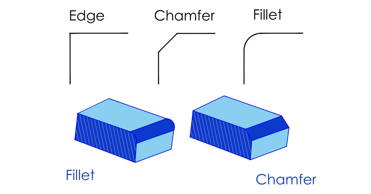
What Does a Fillet Mean?
Fillet refers to a curved or rounded transition between two adjacent surfaces or intersecting edges, creating an arc of defined radius to replace a sharp corner. Machinists often add a fillet edge to the exterior or interior of a part’s edges to avoid sharp edges, strengthen joints, and minimize likely stress and fatigue concentration on components or tools that withstand heavy loads.
This rounded-edge style is a common solution when machining, 3D printing, molding, and casting objects due to its smooth design that eases the sliding of parts. The rounding of an interior corner is called fillet radius. Fillet radius is a standard allowance product designers utilize in casting design to improve product quality and increase load-bearing strength.
Product designers and engineers often create fillet edges through 3D printing or machining a radial tool path. The first involves creating a design with a software program and is programmed to create a surface with an angled slope during the 3D printing operation. Conversely, the latter involves using machining tools to cut a path between two surfaces on your workpiece.

Why Add a Fillet Edge to a Part?
Adding fillets to part design helps improve mechanical stress flow and resist deformation when there is a change in direction on a part to prevent early failure. Fillet engineering is especially crucial in fatigue-prone or load-bearing components since it spreads stress over a larger surface in high-stress areas and creates less friction.
Hence, it delays fatigue in your machined parts to maintain structural integrity and improve their load-bearing capacity.
What Does a Fillet Edge Look Like?
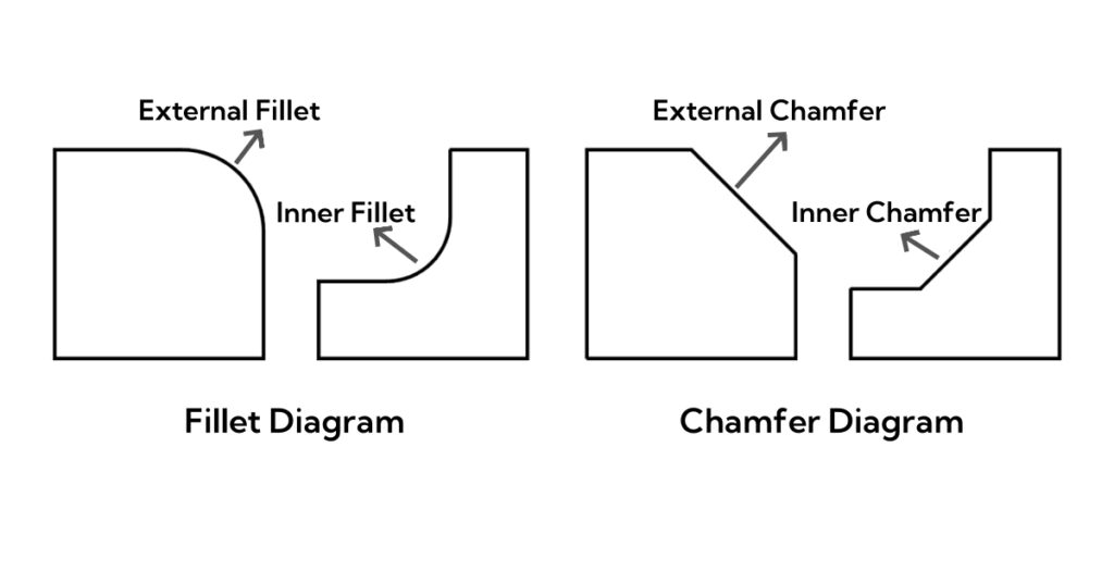
Aside from the fact that fillets reduce stress concentration in edges, they enhance the CNC part’s appearance with its softer and rounded edges. The filleted edge looks convex and rounded on the outside edges, while it appears concave and rounded on the interior surface.
This edge style provides a finish that appears seamless from all angles. However, incorporating this fillet edge in your part design for aesthetics may increase manufacturing costs and machining time for subtractive processes like CNC machining.
Although most often mistake the fillet edge for the beveled edge, there are two distinct edges. While a fillet is rounded, a bevel is a diagonal cut often used to permanently seal or weld two parts to form a strong and effective joint. Filleted edges are often more appealing. They remove potentially harmful sharp corners and burrs from the exterior surfaces of an object while creating a seamless, well-blended joint when used for interior surfaces.

How to Specify Fillet Edge in AutoCAD?
CNC programmers or machinists use the “FILLET” command to specify a fillet in AutoCAD®. To do this, you have to select two lines in your part design that intersect at an interior or exterior corner. Then, input the radius size that will create the fillet. The software program will automatically adjust the length of the chosen lines, create the fillet, and eliminate sharp edges.
What Does Chamfer Mean?

Chamfer is another commonly used type of edge that minimizes stress in parts by altering the rapid change in the contour. Chamfers can be flat, sloped, or angled edges between two surfaces of an object. This sloped edge is often used in structural and mechanical engineering, especially in assembling mating parts at any chosen angle.
Machinists often use CNC machines to add chamfers to a part, and can cut them by hand. Also, you can make it easier for certain 3D printers and CNC machines to produce chamfers when you include it in the CAD programs. Chamfered edges are quite easy to cut and are more economical to produce since they do not require a radius.
Why Add a Chamfer to a Part Design?
Chamfered edges help buffer the original sharp edges to ease part assembly, improve edge safety, and aesthetics. Depending on the application, engineers use a 45-degree chamfer to remove burrs in drilling operations. Chamfer with 60 angle is also widely used for mating parts, especially as a lead-in for a screw and bolt.

What Does a Chamfered Edge Look Like?
Chamfered edges look like a slanted surface that connects the top of a part to another side. You might confuse a tapered edge for a chamfer; when examining the style and look of a chamfer, they are different. A tapered edge has a gradual reduction in dimension over a specific length, while a chamfer is an edge type applied between two surfaces of a part.
How to Add Chamfered Edges in AutoCAD?
You can specify a chamfer in AutoCAD® with the “CHAMFER” command. Input the word “CHAMFER” in the command line and select the two lines in the design that the chamfer will connect. Indicate the angle of the chamfer or the length of the flat face section. Then, AutoCAD® will remove sharp edges automatically and create the chamfer.
Comparing the Difference between Fillets and Chamfers

Even though both fillet and chamfer ease the joining and movement of two or more mating parts, we’ll consider some main points on how they differ.
Fillets are helpful when you need a smooth, curved edge for heavy-load bearing parts to relieve stress in a part. It is beneficial to have high stress concentration edges. Conversely, chamfered edges are ideal for mating parts since you can integrate them in any part design without increasing manufacturing costs or compromising the part’s functionality. Unlike fillets, chamfered edges exhibit poor stress resistance since they cannot distribute stress over a broader surface.
Fillets enhance ergonomics in parts, making them safer to hold or touch, reducing the risk of injury. These rounded edges encourage smoother material flow and reduce disruptions in processes like plastic injection molding, casting, or fluid or airflow designs.
Fillets are considerably more expensive to produce than chamfers. Fillets, specifically internal fillets, are more expensive to machine since they require more complex tooling, meticulous CAD/CAM paths, and multiple passes.
Chamfer edges do not need the same precision levels as cutting a fillet or radius to cut a straight, angled surface. Also, the tool paths for making a chamfered edge are straightforward, and you can create different chamfer sizes with a single tool.
Practical Tips for Fillet Engineering
The following points are crucial considerations in fillet machining:
Design Internal Edges between Vertical Walls
The subtractive principle of CNC milling supports the creation of fillets (rounded corners) between a cavity’s vertical walls. The size of the end mill tool used for the CNC milling often determines the size of the fillets between the walls.
For instance, an end mill tool with a 1.2 mm diameter can create a fillet edge with a radius size as small as 0.6 mm. Unfortunately, it may be impossible to cut a fillet of approximately 0.3 mm if you want to make a cavity with this end mill tool.
When designing fillets in regions where a vertical wall meets an angled or curved wall, you also have to consider the size of the end mill tool. Besides, end mill tools are available in lengths that are multiples of their diameter. Machining experts often use an end mill tool with a length of about 3 to 5 times its size (diameter) to achieve the best results.
CNC Machining Bottomed Edges
CNC machining bottomed edges (concave fillets) can present certain challenges since they require certain specialized tools, including ball end mills. For this reason, it increases manufacturing costs and lead times because ball end mills are high-end CNC cutting tools that are usually fragile and operate at slower cutting speeds.
Hence, machining experts recommend adding square-bottom features in your CNC-machined part’s design. Nevertheless, you might want to consider using an additive manufacturing process (3D printing) to make your part if fillets at the bottom edges are key to the functionality of your product’s design.
How Do You Know When to Use a Fillet or Chamfer?

In this section, we will explore situations when you would want to choose one style of edge that serves your product best.
Here are instances of when to use a fillet edge:
- Parts Will Be Subjected to Heavy Loads: Fillet edges are the perfect choice for load-bearing components due to their low stress concentration factor, thereby preventing rapid deformation.
- Prioritize Functional Benefits over Cost: Even though it is more expensive to create a fillet edge, it would be better to choose this type of edge for your parts if you discover, after specific analysis, that they require properties only a fillet edge can offer.
- Parts Will Be Showcased or Seen: Fillet edges produce an aesthetically pleasing finish on parts. Thus, it might be a viable reason to embrace this edge style if you’ll be putting a specific part on display.
On the other hand, instances in which you would want to choose a chamfer include:
- Prioritize Cost-Efficiency: Chamfered edges cost less since they only require simple tools to produce in a single motion. Therefore, chamfer is a more cost-efficient choice when the benefits that fillets offer aren’t necessary.
- Mating Parts Are Involved: Chamfers are the best when it comes to mating parts. Whether it is for a drive screw, pin, bolt, or other components entirely, chamfered edges provide the smoothest movement and connection between the surfaces of two mating components.
- Absence of Heavy Loads: A chamfer is a style of edge unfit for applications involving high stress concentration or edged parts that carry heavy loads. Hence, you have to examine the amount of pressure or weight the parts will be exposed to.
- Lead-in for Fasteners: When it comes to hole function in part design, a chamfer creates a lead-in for fasteners such as bolts or screws by producing a smooth pin movement and pin insertion. Adding a chamfer around the edge of the hole is a good decision since a fillet can hinder smoother pin movement.
Conclusion
Product manufacturers often have to choose the right style of edge between the fillet and chamfer based on their design and manufacturability for cost effectiveness and efficiency. You may want to choose an edge style that ensures an improved tactile experience and visual appeal of your manufactured parts.
If you need a reputable and capable CNC machining service provider that offers custom design support for fillet and chamfer, AT-Machining is the real deal! Our experienced and certified engineers can meet the engineering specifications requirements of your project. Contact us now for professional assistance for your small batches of product or rapid machining of mating components.