跳到内容
跳到内容 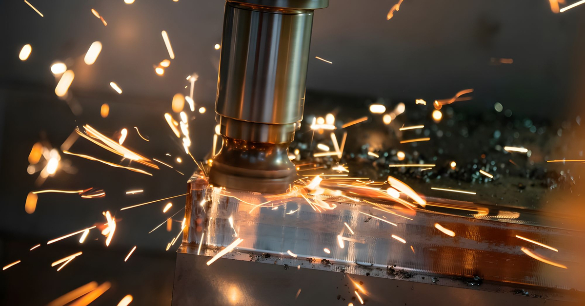
What Is Milling in Machining?
Milling in machining is an archaic term compared to its present use in metalworking. It originates from the use of quern stones to process grain to flour. A set of quern stones comprises a static flat stone and one rotating stone with a hole at its center. The flour is expelled at the circumference as the grain is fed to the hole while the upper quern rotates. This primitive machine was part of the foundation of all rotating machinery.
Milling is a subtractive manufacturing technique that uses a rotary cutter to make consistent cuts on a workpiece material to form the desired shape or features. Modern Milling machines are installed with Computer Numerical Control (CNC) technology, allowing automation control over the machining process.
Origin of Milling Machining
The origin of metal milling dates back to the development of metalworking processes in ancient civilizations when early workers often shaped and manipulated metals into various designs with hand tools like chisels and files.
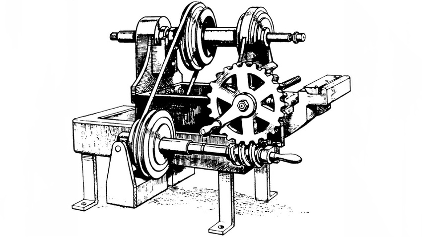
However, the concept of rotary cutting emerged during the Industrial Revolution in the 18th and 19th centuries, following the invention of mechanical milling machines. These early manual milling machines employ rotary cutters to remove metal from workpieces, representing the advent of metal milling as a distinct machining method. Eli Whitney produced the first milling machine in 1818 to manufacture rifles for the US government.
Milling technology has evolved over time, resulting in the development of automated and highly precise milling machines such as computer numerical control (CNC) machines. These modern automated machines have contributed extensively to metalworking and manufacturing industries today.
How Does the Milling Process Work?
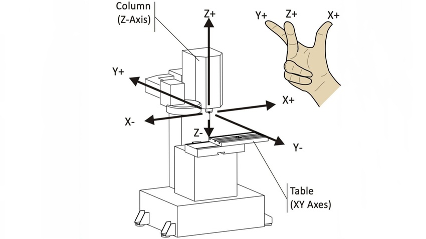
The rotating cutting tools are the main working component of a milling machine. They are responsible for cutting the material into desired shapes. These milling machines can use both single-point and multi-point cutting tools. These CNC machine tools move perpendicular to the rotational axis. A hardened steel or exotic-material CNC cutting tool rotates on a fixed X-Y position, and its position can change in the Z direction.
A workpiece is fastened to a table with various work-holding tools and presented to the cutter. The table can traverse in the X and Y axis by winding position control screws. The workpiece and the spindle axis are set to pass the workpiece across the face of the cutter to remove material. Side cutting of the workpiece occurs as the circumferential faces of the cutting tool bite into the workpiece and are moved in X and Y planes.
The table Z axis or the quill is adjusted for plunge cutting, where the cutter functions as a drill and its face makes a cylindrical hole. This can be the preliminary step in presenting the milling cutter at the required depth to traverse in X and Y to create slots and pockets.
Advanced milling applications can combine the motion of the 3 axes to make compound and simple curvature under CNC path and speed control. Usually, this involves automated cutter exchange and some degree of self-calibration to ensure accuracy.
Other advancements include the ability to rotate the workpiece on the table, tilt the quill to non-vertical positions, and manipulate cutter and workpiece positions in complex and esoteric ways along multiple axes.
Benefits of the Milling Process
Product manufacturers derive a broad range of benefits from milling over alternative manufacturing processes. Below are the expected benefits of milling:
- CNC milling is an automated process that offers the high efficiency required to make high-quality products in mass production runs rapidly.
- Milling offers higher precision and accuracy required in different industries such as aerospace and medical.
- CNC mills can easily cut hard materials like titanium and Inconel, which are usually challenging to machine with alternative technologies.
- The low labor costs and high production rate of the milling process provide cost-effective solutions in product manufacturing.
- The milling process is incredibly versatile; hence, it allows the creation of various complex shapes and features on a wide range of materials.
Stages Involved in the Milling Process
Milling in machining is a sequence of skilled procedures that must be well-executed to achieve desired results. Below is a step-by-step process of milling in machining:
Workpiece Loading
The workpiece loading often ranges from low to highly skilled, depending on the part’s nature and volume. A task usually requires extreme care and precision when the workpiece is held firmly by a vise or bridge clamped into place using T bolts. Poor clamping or misplacement leads to offset cuts, parts breaking out during machine operations, and parts drifting during processing.
Besides, setups can be easy and repeatable whenever higher volume determines the need for specialist nests, even though excellent skills in such custom nest design and part clamping are crucial. However, a dedicated loader built into the CNC machine or a general-purpose robotic setup can handle the workpiece loading in extreme cases where the volume justifies the investment.
Milling Tool Selection
Choosing the right CNC machine tools face for milling operations is a considerably skilled task. The CNC cutters in a CNC machine with a tool changer must be depth-referenced and maintain correct offsets so the machine is aware of the correct offsets and cylindrical positions.
The selection of milling tools in CNC operations will either occur manually by the programmer or as a part of the automated toolpath generation. Moreover, errors in milling tool selections can have catastrophic effects.
Machine Setup
The milling machine setup involves tool selection and clamping as its first stages. Then, you must perform other critical operations. The machine must be taught the workpiece position for a one-off part. Machinist experts often use spatial calibration input methods and devices to reference the material on three sides (for X-Y-Z positioning).
Cutting begins after the material has been loaded and calibrated to the machine’s spatial reference, cutters are set up for length and diametral offset, coolant supply is assured, and the guards are closed.
Milling
Generally, milling is performed on CNC machines of different capabilities ranging from 3 to 6 axes. The cutter tool requires a similar degree of care and attention, whether the process is manual or programmed. The machinist will either monitor the CNC milling process as the machine performs the cutting or operate the machine axes manually to direct the cutter according to the plan. A manual milling machine requires machinists’s full engagement with all parts. This includes consistently stopping operations to inspect the dimensions of the workpiece, ensuring correct operations, and planning the subsequent cuts.
Roughing
Material roughing involves making deep and quick cuts that remove enough materials. It is usually done at a high feed rate and cutting speed to get the workpiece close to the required shape.
Semi-Finishing
Semi-finishing includes making shallower cuts at lower feed speeds to impose higher accuracy.
Finishing
Finishing cuts are fine and fed slowly to ensure the required precision. Some areas often require only roughing, while others require the best possible tolerances produced by slow-moving and fine cuts. Finishing in milling operations is usually slow and time-consuming, taking most of the machine’s time per part.
Unloading
Unloading the workpiece involves releasing the clamps that engage the workpiece and removing it manually or by a robot. Machine cleaning is generally performed at this stage to prepare the machine for its subsequent use.
Inspection and Quality Control
Quality control experts manually perform measurements and surface quality evaluations or use advanced inspection equipment. However, you can sometimes undertake fully automated inspections for particularly high-volume parts.
Post-processing
Standard post-processing after milling includes simple deburring and packaging for storage or future use. Similarly, it can involve different heat treatment types, chemical surface treatments, surface coatings, or plating.
Typical Milling Operations
Milling operations are of various types, each with the ability to create different components with varying shapes. Common milling operations include:
CNC Milling
CNC is a milling operation that uses computer programs to dictate the cutting tool’s movement. It can produce parts with intricate designs and geometries at faster speeds. However, there are multiple axes options for CNC milling machines depending on the complexity of the intended workpiece.
Slot Milling
Slot milling, or groove milling, involves making grooves in a workpiece with a long rotary cutting tool. These slots made with this machining technique are typically deeper than what end mills can produce. With several options for shape, the grooves can be either open or closed.
End Milling
An end mill has a similar shape to a drill bit. Besides, end mills can cut axially and radially. However, a drilling machine only cuts in the axial direction, while a conventional milling machine only cuts radially.
Face Milling
This process involves smoothening the surface of a workpiece with a face mill for the desired surface finish. A face mill can make uneven surfaces flat and with a smooth finish. Moreover, there are different manual and automatic milling options for face milling.
Chamfer Milling
Machinists use chamfer milling to make bevels and chamfers in a workpiece. A chamfer mill or chamfer cutter has other applications, including spotting, deburring, and countersinking.
Helical Milling
Helical milling makes helical pathways, holes, and channels in cylindrical workpieces. The workpiece is clamped to a rotary table while the rotating cutter moves along a helix angle along the workpiece. Machinists employ helical milling to create lubrication holes and paths on a workpiece.
Profile Milling
Profile milling is a standard finishing operation used when machining vertically inclined surfaces. It is often applicable in the rough operations and the finishing stage. However, roughing or finishing operations determine the choice of cutting tools in profile milling.
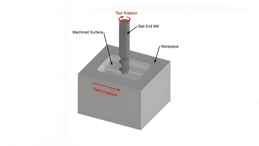
Plunge Milling
The Feed is in the same direction as the tool axis as the tool axis in plunge milling. This milling operation, also called z-axis milling, is a commonly used process in roughing. The cutter digs deep into the workpiece and carves out pockets in the workpiece material.
Climb Milling
The climb milling process uses a cutting tool that rotates in the feed direction. It is the opposite of conventional milling operations, where the cutter rotates in the opposite direction as the feed. The cutting tool mounts the workpiece, accumulating chips behind it. It eliminates the issue of chips obstructing the cutting tool.
Thread Milling
Thread milling involves making threads inside a workpiece. However, a thread mill works only on predrilled holes. The thread mill rotates and revolves around the workpiece’s interior surface.
Peripheral Milling
Peripheral milling involves placing the cutting tool parallel to the workpiece as the tool’s sides grind against the workpiece surface instead of the tool’s tip. Peripheral milling is the opposite of face milling. It is often suitable for removing large amounts of material from the workpiece.
Types of Milling Machines
Milling machines are available in different types, each with a unique design and several components to handle particular milling tasks and workpiece sizes. Below are common types of milling machines:
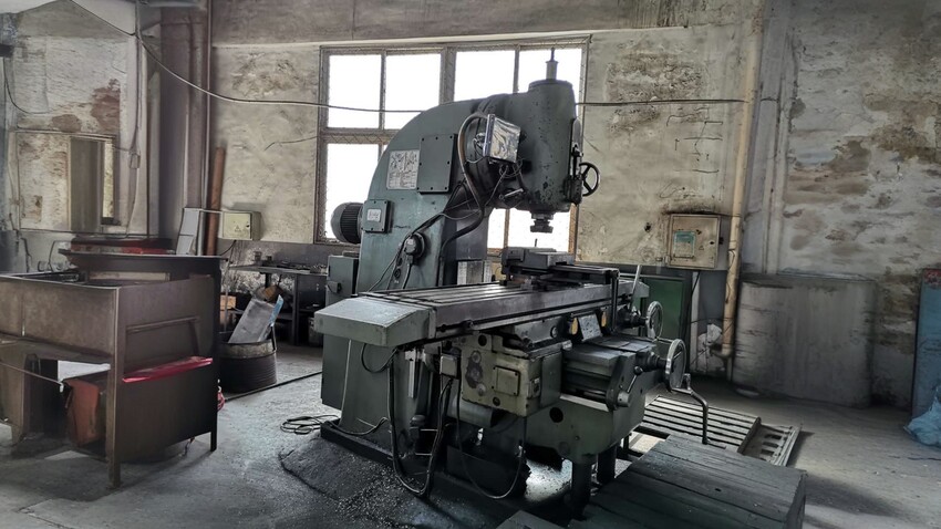
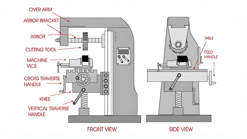
Horizontal Milling Machines
These are milling machines with horizontally positioned spindle axis. Most milling machines use horizontal mills that use rotary tables for milling at varying angles. They are often called universal tables. Although a horizontal mill is suitable for heavy milling operations, it is less versatile than a vertical mill.
Vertical Milling Machines
A vertical milling machine has a spindle axis or quill with a vertical orientation. It is a versatile machine primarily suitable for machining operations like end milling and face milling of smaller workpieces.
Universal Mill
A universal milling machine has a rotary table that can modify the workpiece presentation angle. It provides greater versatility in milling operations.
Bed Mill
This milling machine features a stationary bed that supports the workpiece while only the workpiece and the spindle move. It accommodates larger and heavier workpieces without requiring extreme axis drivers.
Turret Mill
Turret mills are similar to vertical mills but feature a turret-style tool head. Multiple cutting tools are available as the turret rotates, allowing for precise and consistent cuts.
Knee Mill
A vertical spindle with an adjustable knee offers variation in the spindle’s angle, allowing greater range in the worktable’s vertical position.
Gantry Mill
This movable bridge structure supports the spindle drive—only the tool cutter moves, allowing easy machining of large and heavy workpieces.
Basic Parameters in Milling Machining
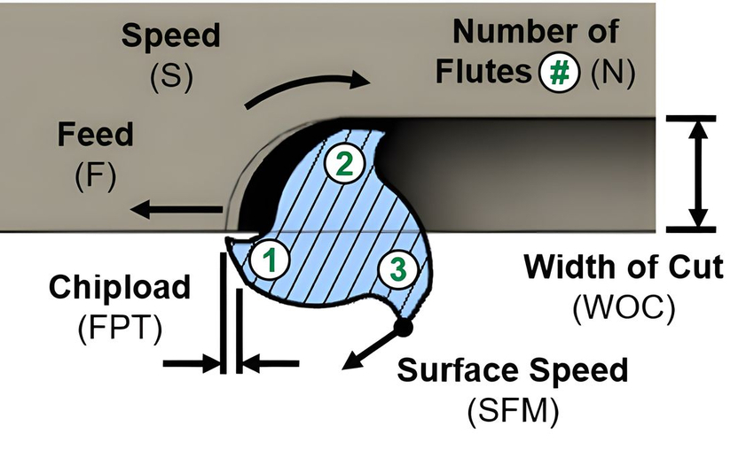
This section explores the different key parameters to consider in milling machining processes:
- Feed Rate: The feed rate is the relative movement speed between the cutter and workpiece during milling operations. This value is measured in inches per minute (IPS or in/min) or millimeters per minute (mm/min).
- Spindle Speed: Spindle speed is the relative speed at which the cutter (or spindle) rotates. It is calculated in revolutions per minute (RPM). The tool cuts faster with a higher spindle speed and removes a material at a higher rate.
- Depth of Cut: Depth cut measures the vertical thickness of material removed in a single pass. It is recorded millimeters or inches—a higher depth of cut results in slower cut and higher tool wear.
- Axial Depth of Cut: Axial depth of cut refers to the length of cut measured axially in the cutting tool’s direction. Also, this value is the cut’s width in a single pass, and it determines the thickness of the chip.
- Radial Depth of Cut: The radial depth is the diameter of the cut on the workpiece material and is measured along the cutting tool’s radius. It determines the milling tool’s deflection.
- Cutting Speed: It indicates the rate at which the milling machine tool moves along the workpiece. This value is calculated by multiplying the tool’s circumference with the spindle speed. This value is often measured in meters per minute (m/min) or surface feet per minute (SFM).
- Stepover: This refers to the distance between two consecutive passes during milling. Too low a stepover can lead to interfering cuts, resulting in poor precision and machining errors.
- Ramp Angle: Ramp angle is the contact angle between the workpiece and the milling tool during entering. This is a commonly used angle in ramping operations.
- Tool Diameter: The tool is the specific milling cutter’s diameter, usually measured in millimeters or inches. Tool diameter determines the cutting force, dimensions to cut, and chip removal.
- Tool Overhang: This is the distance between the tool edge and the holder. It can be seen as the tool’s functional length—a larger tool overhang results in higher vibrations, tool wear, and reduced stability.
- Tool Coating: Milling tools are covered with special coatings to improve their cutting quality and reduce tool wear. Typical tool coatings include Titanium Aluminum Nitride (TiAlN), Diamond-Like Carbon (DLC), and Titanium Nitride (TiN).
- Coolant Flow Rate: This is the rate at which the cutting fluid flows to the cutting zone. The coolant flow rate is regulated according to the feed rate and cutting speed.
What Industries Use Milling?
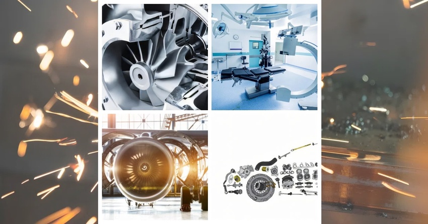
Milling applies to different industries and plays a pivotal role in manufacturing various products. For instance, milling high-value, lightweight, and complex parts for different aspects of flight-engineered products is widely undertaken in the aerospace industry. The multi-axis CNC milling is the standard production process for most parts, ranging from flight-surface actuator parts to jet and rocket-engine components and airframe components.
Milling is widely embraced in the production of medical tools and medical implants. The ability to machine various biocompatible and easily sterilized materials with high precision and repeatability is highly valued in these high-value applications.
Hazards in the Milling Process
Although the milling process is mainly automated, there are some common milling hazards you should consider. Here are common milling hazards:
- Electrical Hazard: Milling machines utilize incredibly high voltage. Hence, shielding all electrical parts with guards and labeling them as electrical hazards is critical.
- Sharp Cutter: The cutters of milling machines have multiple cutting edges that are very sharp and rotate at very high speeds. The milling cutters or any other rotary machine part should never be exposed or come in contact with humans during milling operations.
- Heat: Milling operations generate incredibly high temperatures that should not make contact with humans. The workpiece can retain the high temperature for a while after the operation has been halted. Therefore, it is essential to handle the parts with gloves.
- Chips: Milling removes unwanted material from a workpiece in the form of chips. These chips often fly at a high speed and can pierce the skin or other sensitive organs, such as the eyes.
- Noise: Like other industrial equipment, milling machines generate high noise levels. Hence, it would be best if you got proper noise-canceling ear protection.
Conclusion
Milling is one of the most widely embraced processes in machining due to its cost-effective and precision benefits. The wide variety of milling operations allows the creation of parts of any preferred shape, making the technology a preferred solution in metalworking. This guide has discussed everything you need to know to make an informed decision about your next milling project.
AT-Machining is a one-stop CNC milling services expert in China. We leverage our modern CNC factories with cutting-edge multi-axis CNC milling machines to deliver top-quality, custom-milled parts with precise tolerances. Our certified and experienced QC and QA teams oversee all CNC milling operations to ensure your parts meet client specifications and quality standards. Submit your CAD file design to our reliable online quotation platform for instant quotes!