跳到内容
跳到内容 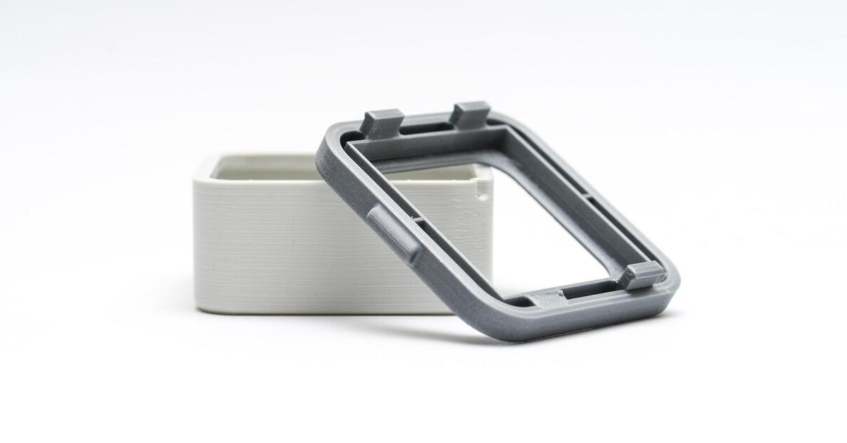
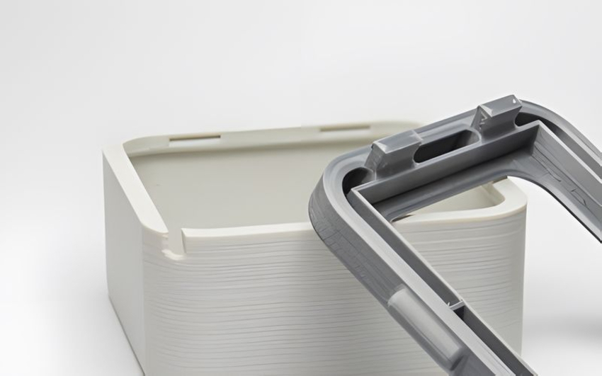
What Is Snap-Fit Joint Design?
A snap-fit joint design is a primary method for fast and seamless assembly and disassembling of parts without additional tools or fasteners. The joint comprises a male part (usually the bump or head) that can interlock or deflect to pair with the female part (a depression) to form an assembly. This simple design allows the creation of assemblies by applying a moderate force on the joint’s flex or male part.
Snap-fit components don’t need other fasteners to join or hold them together. More importantly, they are reusable and offer better disassembling without damaging the assembled parts or losing quality. These joint mechanisms are usually flexible. They are capable of temporarily deforming and returning to their original shape damaging. As a result, plastics are the typical material for making snap joints due to their durability and flexibility.
Types of Snap Fit Joints
This section discusses the different types of snap-fit joints suited for different machining processes:
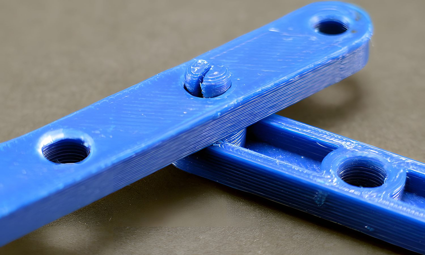
Cantilever Snap-Fit Joints
These joints are the most widely used snap-fit joint among all the other snap-fits. They have simple geometric shapes that facilitate their implementation ease in a snap-fit design. Also, you can quickly determine their strain during the joining procedure.
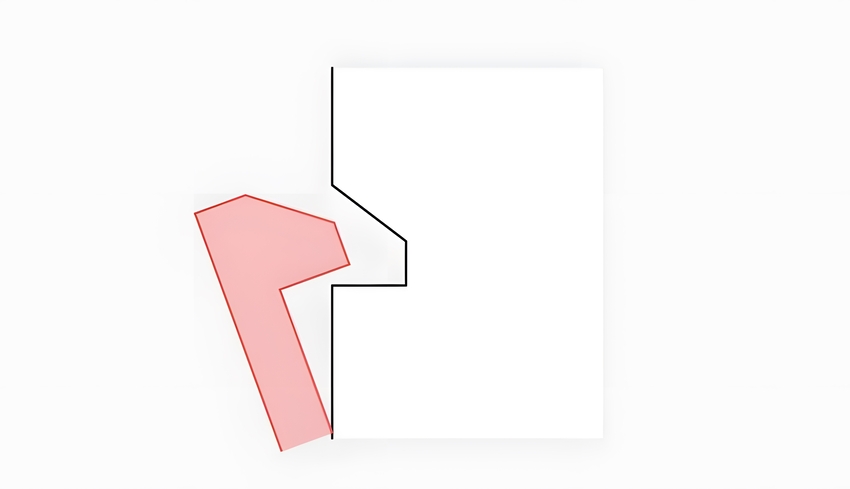
The cantilever snap-fit has a basic design featuring a cantilever beam, a sharp hook at its free end, and a joining partner with a matching recess. The tapered hook slides across the opening on the female or joining partner’s surface, bending the cantilever so the hook can reach the recess before returning to its initial state.
The cantilever joint often remains permanent till a separation force releases it. These design snap-fit joints are suitable for fastening two similar halves that require easy disassembling. The cantilever doesn’t always come in the straight bar form; other designs include U- or L-shaped cantilevers commonly seen in plastic parts.
Annular Snap-Fit Joints
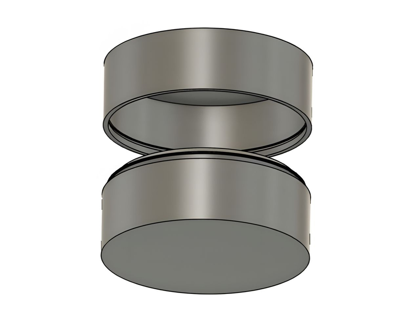
Annular snap-fit joints consist of a circular hoop that extends when pushed onto a rigid, complementing hollow or indentation. Annular snap joints are suitable for circular- or cylindrical-shaped parts and often feature container lids and pen caps.
One of the components (the male) in the assembly features a ridge at the circumference, which corresponds to or locks into the groove of the tube-shaped second part (female). Annular snap-fit joints provide uniform stress distribution in annular shapes, making them suitable for assembling lamp housing, plastic containers, snap-on caps, or other high-stress applications.
However, stress such as multiaxial stresses occurs in the annular hoop due to the expansion, resulting in enough frictional force that holds it at the top of the groove structure. Furthermore, this snap fitting can lose its fitting over time due to overuse and hyper-extension.
Torsion Snap-Fit Joints
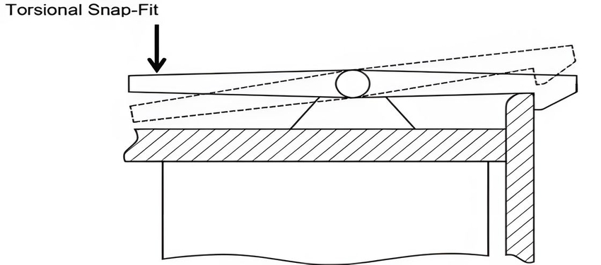
Torsion snap joints employ a twisting mechanism to make a secure fit or disassemble it from another component. The torsion snap joints have interlocking beams similar to the cantilever snap-fit joints but rely on a spring mechanism to assemble or secure the parts.
For instance, torsion snap fits have a spring-loaded lever on one of the components needing assembly. When you force the mating parts against each other, the spring force snaps into position.
These torsional snaps function like a seesaw; the beam deflects into position when you insert the part with a groove. These snap-fit joints are suitable for components that require frequent disassembling or temporary connections, such as fastening hinged lids on containers.
Common Applications of Snap-Fit Design
The snap fit joints have extensive applications in custom machining, being useful in various industries like automotive, electronics, aerospace, and others. For instance, the automotive sector uses snap fittings as a simple substitute for heavy fastening mechanisms. Below are typical uses of the snap-fit design:
- Pens: Pen caps are typical examples of annular fits. However, they often require pressing them on the pen top to open up and connect with the pen tightly.
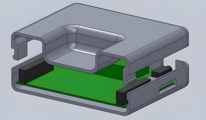
- Consumer Electronics: Snap fits have common use in consumer electronic devices like laptops, tablets, and smartphones. Additionally, various electronic enclosures like Ethernet boxes and USB hubs use snap-fit connections.
- Toys and Games: An effective fastening mechanism is an ideal part of toy molds. The snap-fit joints are suitable for toy making because they must be cheap, lightweight, and mass-produced. Snap fitting allows assembling different parts in building blocks, toys, puzzles, and model kits.
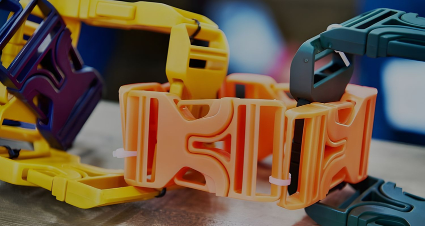
- Strap Buckles: Snap fittings have common use in buckles used on camping accessories, tie-down straps, and most bags.
- Home Appliances: Snap-fit connections have common use in household appliances such as power tools, kitchen appliances, and vacuum cleaners. These joint designs secure different parts, enabling maintenance ease and quick assembling.
Snap Fit Design Calculations
The preferred snap-fit design type often determines the ideal calculations for your design. It would help to consider parameters like deflection force and maximum stress in determining the snap-fit joint’s dimension. This section gives a detailed illustration of practical calculations for your snap-fit design:
Cantilever Snap Joints
It would be best to consider parameters such as bending/deformation, strain, and deflection in designing a cantilever snap joint.
- To calculate the maximum bending stress, use the following:
σmax = mc / I
Where M is the maximum bending moment
C is the distance between the point of interest to the neutral axis
I is the moment of inertia
- To calculate the maximum strain, use the following:
ε = M / IE
where E is the material’s Young’s modulus
- Calculate constant cross-sectioned beam deflection using:
y=0.67 * εl² / h
where l is the beam’s length
h is the thickness at the root
- Calculate deflection force using:
P=bh² / 6 · Es ε / l
where b is the width at the root
Es is the secant modulus
Annular Snap Joints
Annular snap fittings are perfect for cylindrical-shaped parts, featuring one rigid mating component. Below are formulas for annular snap fits design:
- Transverse force:
P= y · d· Es · x
where y = undercut
d = diameter at the joint
Es = secant modulus
X = geometric factor
- Mating force:
W=p · µ+tan (σ)/1-tan (σ)
where µ = coefficient of friction
α = lead angle
Torsion Snap Joints
- The shear modulus:
G-Es / 2(1+V)
where G is the shear modulus
Es is the secant modulus
V is Poisson’s ratio
- The deflection force:
P · l = YGIp / r
where Y is the shear strain
Ip is the polar moment of inertia
W = p +tan(σ) / 1-tan (σ)
W = 13.98 · 0.72+tan(30)/1-tan(30)
W=42.91 N
Symbols:
- c = center of gravity (i.e., the distance between the neutral fiber and the outer fiber)
- E = permissible strain in the outer fiber at the root
- σ = twist angle (radians)
- b = width at the root
- h = thickness at the root
- Es = secant modulus
- E as absolute value = percentage/100
- y = permissible deflection (=undercut)
- k = geometric factor
- p = permissible deflection force
- l = length of the arm
- z = l c; where l = axial moment of inertia
- z = section modulus
Snap-fit joints are a versatile and cost-efficient solution in plastic parts assembly. AT-Machining is your ideal partner whenever you need professional assistance with your designs or prototype parts.
Common Snap Fit Design Challenges and Solutions
Although the snap-fit design is critical, it is not a one-solution fits all process; certain challenges arise during the 3D printing or injection molding of snap-fits. Below are some of the common challenges encountered when designing snap-fit joints and solutions:
Creep Occurrence / Stress Relaxation
Plastic resins, especially thermoplastics, are vulnerable to creeping. They gradually deform when subjected to extreme stress. Then, the creep compromises the connection between the components (male and female parts), rendering them useless.
However, design both parts so that depression may usually occur during assembly or in assembled use. Furthermore, ensure the parts are not exposed to extreme bending or tensile stress.
Stress Concentrations
There are higher chances of stress concentration at the root of the cantilever snap joint when there are sharp corners or points of engagement. As a result, this reduces the material’s strength and makes the cantilever vulnerable to shearing off.
Employ chamfers or radii to mitigate the risk of shearing. Eliminate all sharp corners that could act as stress concentrators, especially on the cantilever’s side,
Tolerance Issues
Tolerance issues usually happen when gaps are wrongly placed. This is because when components fail to fit together correctly, tolerance becomes a problem.
Consider using the rule of thumb for gaps such as:
- 0.2 mm for tight fits
- 0.3 mm for close-fit snap joints
- 0.4 mm for slide pivot joints and slide fits
Material Selection
It is crucial to choose a suitable material for your snap-fit joint design. This is because complications such as dimensional issues, poor fit, or excessive stress can occur due to mismatched material properties like different coefficients of thermal expansion. Hence, evaluating the material’s compatibility is crucial to ensure it possesses the required strength, durability, and flexibility for the intended application.
Engineering Best Practices for Snap Fit Design

Several design properties can help reduce stress and strain on the joint assembly. This section discusses the best engineering practices for practical snap-fit designs:
Taper the Design
A good design practice reduces the cross-sectional area of the cantilever beam over its length. You can increase the joint’s longevity by simply tapering along the snap fit’s length. Tapering a design ensures less material use and uniform stress distribution in the material, ensuring reduced manufacturing costs. Uneven strain distribution often causes failure in snap-fit joints.
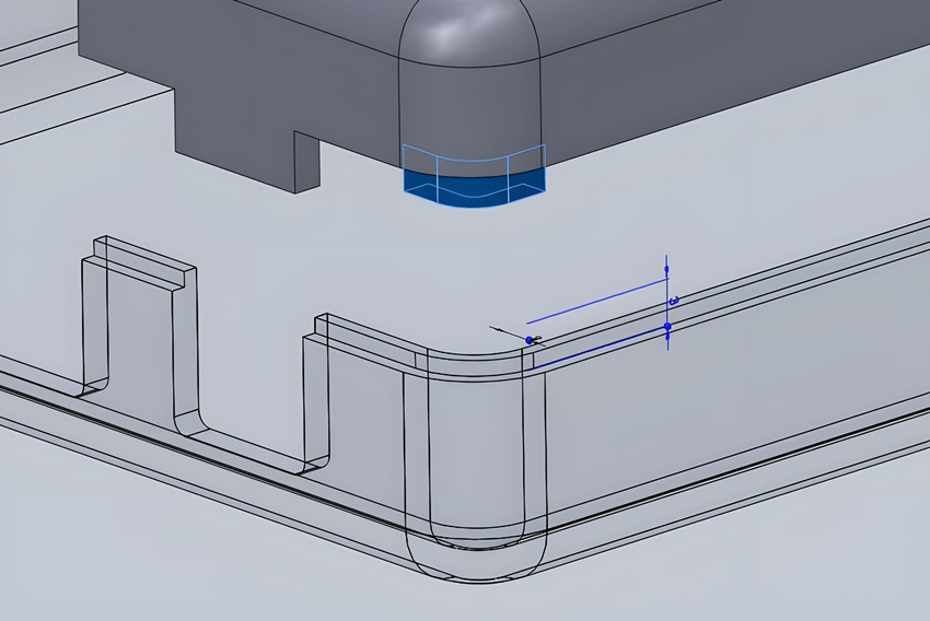
Add Fillet at the Base of the Cantilever
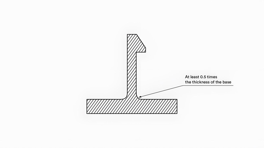
It is essential to eliminate sharp corners in your cantilever snap-fit joint design to prevent concentrated stress or load. You can efficiently distribute structural stress over a broader component area and establish a stronger connection by attaching a fillet to the cantilever’s base. Maintain an ideal fillet radius not less than 0.5 times the thickness of the cantilever base.
Increase the Width of the Clip
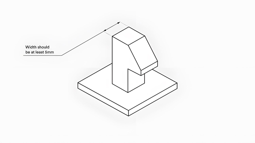
Increased clip width strengthens the snap-fit joints. Snap-fit designs with increased clip width resist high loading frequencies more and achieve a suitable stiffness level. However, the standard clip width should be at least 5mm.
Consider Adding Lugs
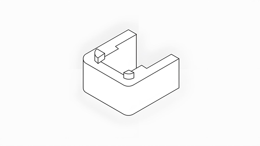
High-quality components often feature lugs since adding lugs in parts assembly help to keep them aligned. Likewise, these tiny protruding connectors offer structural support by transferring some shear force from the clips.
Consider the Build Direction
Avoid building the snap-fit joint design in a vertical direction from the bed. The designing process is anisotropic, and the snap joint designs constructed from the bed vertically are often weaker. The cantilever snap fits and other types should deflect during assembly, not during component connection.
Fatigue Life
Fatigue stress is a significant challenge in snap fitting with faulty design considerations. Fatigue failure is common with frequently disassembled snap fits due to consistent loading. Hence, it is advisable to choose materials with excellent yield strength and make geometric considerations that mitigate risks of fatigue failure.
AT-Machining: A Reliable Machine Shop for Quality Snap-Fit Joint Design and Manufacturing
Snap-fit joint designs are crucial in product manufacturing because they offer reliable, easy fastening, and cost-effective mechanical joints. These joints enhance products’ aesthetics, assembly, and strength according to the designs and intended application. However, choosing a manufacturing partner will influence your snap fittings design and manufacturing success.
AT-Machining is a reliable machine shop that offers high-quality plastic and metal snap-fit joints for your products. Our technicians provide professional assistance from prototyping to part production. Our extensive machining capabilities allow us to realize your design ideas exactly as specifications. Submit your design file today; let’s start your next project!