跳到内容
跳到内容 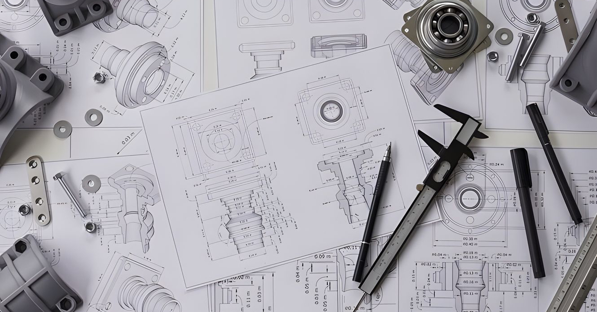
What Is a Technical CNC Machining Drawing?
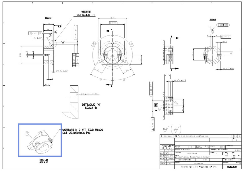
A technical or machining drawing clearly and precisely represents a design idea generated with computer-aided design (CAD) software. Machining drawings usually include all necessary materials, basic dimensions, and measurements, serving as the framework for the machining process. CAD software also facilitates the precise and accurate incorporation of complex shapes, intricate details, and multiple angles into a product’s design. Moreover, technical CNC machining drawings are critical to engineering, architecture, and manufacturing because of their high accuracy and precision requirements.
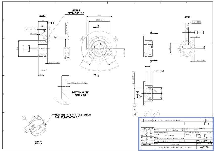
Basic Anatomy of a Technical CNC Drawing
Generally, CNC machining drawings require different tools and methods to effectively create accurate diagrams, blueprints, and other visual representations of a mechanical design. Here are some of the essential components of a CNC technical drawing:
Title Block
The title block provides pertinent information like the author, title, date, and other critical details about a CNC drawing. This aspect of the machining drawing also includes the scale of the drawing, which is principal to ensuring the accuracy of dimensions and measurements. The information in the title block is crucial in CNC machining projects where the most insignificant error in measurement can have huge effects. Moreover, you can include additional notes and specifications to further aid in the interpretation and use of machining drawings.
Detail Views
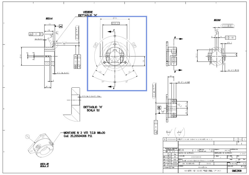
These views allow a closer look at specific features of a part or assembly, providing crucial information on tolerances, dimensions, and surface finishes. Since precision is critical to CNC machining, detail views allow machinists and product engineers to ensure the accuracy of each detail of a part and that it is up to standard.
Detail views facilitate explicit communication between product manufacturers and designers, ensuring everyone works towards the same goal. Product designers ensure that their parts are produced and match the specifications, with no room for error, by adding detailed views in your machining drawings.
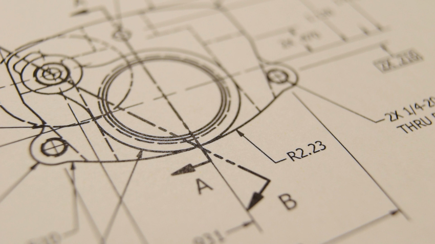
Coordinates
Coordinates are groups of letters or numbers that correspond with specific points on a plane or grid. Product designers often employ two major coordinate types to make accurate and detailed designs in CNC machining drawings. These include polar coordinates and cartesian coordinates.
Polar coordinates indicate an object’s location with angles and distances, while cartesian coordinates determine the position of an object with vertical and horizontal lines. These coordinates are pivotal to machining drawing, enabling the clear and concise representation of a design idea.
Isometric Views
This view lets you make 3D representations of your product designs on two-dimensional depictions. The isometric view is instrumental in cases where precision is critical. It helps to understand better how interlocking components assemble or fit perfectly and how they function within a larger structure or assembly.
The isometric view helps save time and mitigate possible errors during the CNC machining process. It is an essential tool in modern manufacturing because it can convey technical details and spatial relationships simultaneously.
Orthographic Views
Orthographic views provide a three-dimensional object’s front, side, and top views. These views are necessary for accurate CNC machining design drafting. Without these views, product designers and engineers would find it challenging to convey critical dimensions and shapes for producing precise parts.
Similarly, these views provide essential information on the placement of different design features like slots and holes with overall dimensions of the machined part. CNC machines can fabricate complex parts with high accuracy and consistency using detailed orthographic views.
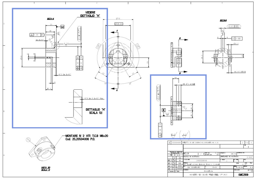
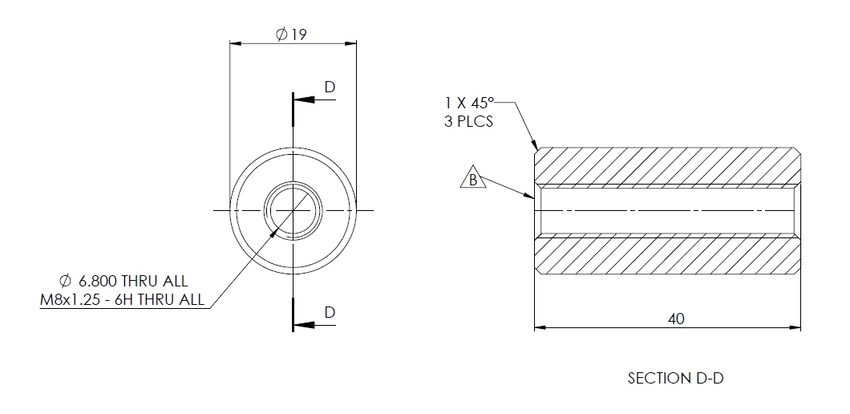
Section Views
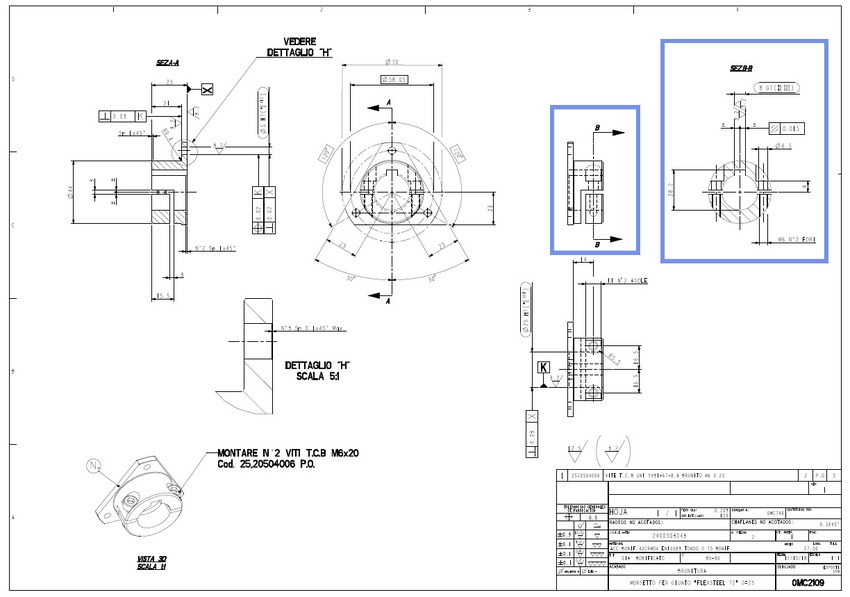
Section views facilitate a better understanding of the internal workings of a part critical to ensuring its accurate and efficient machining. It portrays cross-sections of the part at crucial points to help identify potential design flaws or defects that may influence the component’s functionality.
These views are helpful in machining process optimization and ensuring the end product meets all the specifications. However, when you include section views in machining drawings, product engineers and machinists can work together to achieve top-quality, precise parts that surpass expectations.
Note to the Manufacturer
When drafting a CNC machining drawing, it is essential to include pertinent notes for manufacturers. It helps them to create desired components accurately since it comprises critical information not contained in the blueprints, like required material, tolerance specification, surface finish requirements, and other special instructions. It is usually represented in symbols instead of texts, like the surface roughness symbol, indicating the specific finishing requirement. Moreover, ensure that the required number of parts and production timeline are specified.
A Stepwise Guide to Preparing a Machining Drawing
CNC machining drawings are primary to any machining process. It is essential to understand the structure of the CNC machining drawings. Here is a stepwise guide:
- Step 1: Define the most critical views and position the relevant orthographic at the drawing’s center with enough space between them for the dimension details. Also, do not use excess hidden lines to avoid confusion and disorganization in the drawings.
- Step 2: Add section or detail views if your part has complex internal features and difficult-to-dimension areas. The section views offer a 2D projection that provides a better view of intricate dimensions and hidden features that may not be evident externally.
- Step 3: Include construction lines to all views. These construction lines often include center mark and center mark patterns (to indicate the center’s location of circular patterns or holes) and centerlines (to show axes or planes of symmetry).
- Step 4: Add critical dimensions to your engineering drawing and ensure the dimension lines and figures are explicitly specified on the drawing without crossing one other.
- Step 5: Specify the size, location, and length of all threads. Consider using a hole callout instead of dimensioning all the hole’s aspects. It specifies the diameter and depth of the hole in the presence of a countersink or counterbore, including the depth of these features.
- Step 6: Add tolerances to features that require higher accuracy than the standard tolerance.
- Step 7: Fill out the title block and ensure all key information and requirements surpassing standard practices are stated in the additional notes. So, export the drawing as a PDF file and attach it to your order when ready.
Why Prepare Technical Drawings When Sourcing Parts?
Engineering or technical drawings are core to product manufacturing. They have been in existence for centuries before the recent digital manufacturing technologies. These drawings provide essential information such as technical information and engineering design during the machining process of a product. Technical drawings are used in CNC machining to create accurate parts, reduce costs, and improve communication between machinists, product designers, and manufacturers.
Before the advent of computers, technical drawings were the principal reference point for manufacturers. However, nowadays, product teams can design a part on a computer and share it with a CNC machine that will fabricate the item without necessarily creating a technical drawing. However, why do you need a technical drawing for your manufacturing project? Here are some of the reasons why you need a technical drawing in manufacturing jobs:
Validation
Machining or technical drawings help verify details of the CAD file, providing confidence to product manufacturers that they are on the right track in fabricating a product precisely to specification. If the CAD file matches the machining drawing perfectly, there are no errors in the design.
Quick Reference Point
Most product manufacturers prefer to receive technical documents with a digital file because the technical drawings serve as a reference for inspection once the part has been completed. These drawings help assess aspects of the part, including its numerical values, geometry, and potential costs.
Additional Information
Technical drawings present much other information not included in a CAD file. Technical drawings may often include other relevant details, such as material specifications for particular components, internal or external threads, specific feature tolerances, and individual surface finishing requirements.
Legal Instrument
Machining drawings can perform a legal function. These technical drawings for CNC are included in a purchase order; hence, they are a part of a contract. So, the failure of a manufacturer to deliver the part precisely to specifications, the drawing shows that the design has not been fulfilled. Meanwhile, the manufacturer is protected from liability provided it adheres to the drawings submitted.
Globally Recognized
Technical drawings are the only means of conveying engineering instructions that are recognized at the international level. There is no confusion, ambiguity, or potential complications that can compromise the project’s success.
Why Are Precision and Accuracy Crucial in Machining Drawings?
Since CNC machining drawings convey the design of a part between the manufacturers, designers, and engineers, there is no room for errors that can cause the machined part not to meet the required specifications. Below are reasons why precision and accuracy are key to technical drawings in the machining industry:
Waste Reduction
Machining parts that fail to meet the required specifications potentially wastes materials, time, and effort. Accurately precise technical drawings reduce wastage by ensuring the product is machined appropriately. Hence, this reduces the need to rework a component, which can be costly.
Meeting Quality Standards
Manufacturers can meet stringent quality standards with accurate and precise technical drawings. Fabricating parts to the required design specifications also helps to avoid errors or defects that can cause failure and ensure machined parts function correctly.
Ensuring Product Functionality
Machinists can easily create parts that function as expected when the details on the technical drawings are accurate and precise. A part will not work as it should if any deviation from the required specification results in potential complications down the production line.
Common Standards for Machining Drawings
Machining and engineering drawings are subject to different commonly acknowledged sets of standards. These standards guide technical drawing presentations, facilitating effective communication between parties.
The American Society of Mechanical Engineers specifies its drawing standards as Y14.5 and Y14.5M. The International Organization for Standardization recommends using ISO 8015 for engineering drawings and ISO 128 for technical drawings.
Following the ISO document, ISO 128 provides general rules for technical drawing execution and applies to machining drawings in mechanical engineering, shipbuilding, construction, and architecture.
How to Add Threads to a Machining Drawing
It is compulsory to indicate and define threads on the drawing for CNC machining if your parts contain them. You should define these threads by indicating a standard thread size like M4x0.7 instead of a diameter dimension. Ensure you provide detailed thread callouts to clarify the drawing and permit the specification of pilot holes and threads with varying lengths.
- The first operation is to designate the thread type, size, and pitch.
- Define the thread specifications using appropriate symbols or annotation. These symbols usually include a triangle with parallel lines within, which portray the thread’s V-shaped grooves. The thread’s pitch is generally indicated next to the symbol.
- Ensure the thread is placed in the appropriate location and proportioned accurately to the rest of the drawing.
How Do You Add Hole Callouts in a Technical Drawing for CNC?
Including hole callouts in a technical drawing is essential to making detailed and precise documentation for manufacturing purposes. A typical hole callout supplies details about the size and position of holes in a particular part. Here are a few steps to follow when adding hole callouts to your technical drawing:
- Identify the hole that requires detailing.
- Make a center line that crosses the hole in the middle and draw an arc showing the circumference of the hole.
- Label the hole with related hole callouts according to the project’s standards and specifications.
- Ensure you include critical features like tolerance, diameter, and hole depth.
How Are Tolerances Specified on a Machining Drawing?
Tolerances are represented using various formats on a main orthographic view. These machining tolerances specify a range of acceptable deviations in the values for a particular part’s dimension. Tolerances are especially important for complex features that interact with other components in assemblies. They are usually of different formats and applicable to any dimension on a CNC machining drawing. For example, bilateral tolerances are the most straightforward and symmetrical around the base dimensions. Unilateral tolerances possess upper and lower limits in the technical drawing.
What Is Geometric Dimensioning & Tolerancing in Technical Drawings?
The Geometric Dimensioning & Tolerancing (GD&T) is an advanced system manufacturers and product designers use to explicitly indicate and communicate machining tolerances. These symbols and specifications in machining drawings share required design specifications, ensuring the manufacturers fabricate parts according to customer preferences. GD&T symbols often include circularity, flatness, straightness, parallelism, position, and perpendicularity.
Traditional dimensioning is often confusing because dimensions are easily misinterpreted between machinists and product designers. Hence, GD&T is critical to precision CNC machining because it facilitates the production of parts with the utmost accuracy and precision. GD&T offers clear guidelines on measuring and creating parts within the allowable tolerances, eliminating any guesswork. Therefore, it ensures optimal efficiency in the production process, ensuring reduced errors and flaws in CNC machined parts.
Helpful Considerations in Preparing Technical Drawings
Here are helpful tips to consider when preparing the ideal machining drawing machine shops will be able to interpret at a glance:
- Use standard templates ISO, ASTM, and DIN since they are the most commonly used templates, and manufacturers and machinists across the globe understand them.
- Place your orthographic projections at the center of the drawing sheet, leaving sufficient space to accommodate the dimensions.
- Consider adding a section view in your machining drawings to reveal hidden features or complex parts.
- Convey different design features with various types of construction lines and dimensions. For example, broken lines make hidden features more visible to machinists.
- Add tolerance values in all critical parts and design features like holes and threads.
- Include additional information or notes that might help the manufacturer with the project.
- Ensure you export the completed technical drawing in PDF format and share it with your manufacturer. Modern machine shops allow you to upload your drawings on their website while they offer a quote for your manufacturing project.
Conclusion
Machining drawings are generally good practice in the product manufacturing industry. It is a core quality control mechanism that enables machinists and inspectors to produce parts precisely to the customer’s specifications. However, there are different technical or engineering drawings, each with a distinct purpose in the product design and manufacturing process. Hence, understanding these machining drawings helps to ensure the dimensions of your product are not misinterpreted at any stage.

AT-Machining is a top CNC machining services expert in China with highly qualified machinists and engineers capable of reading your technical drawings and fabricating your products precisely to specification. Upload your technical drawings via our quote tool and get instant quotes for your project. Let our experts analyze the technical drawings for your next project and provide professional design advice for efficient and cost-effective production.