Skip to content
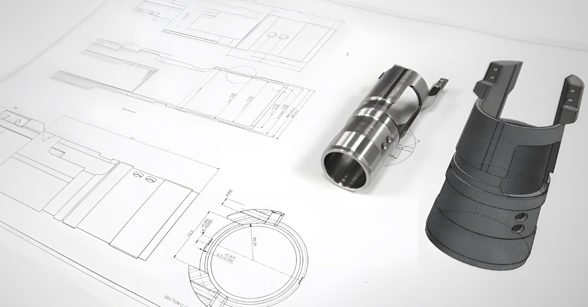
Overview of CNC Machining
A product’s development begins with the initial concept and then transitions to the physical form through a precise and cutting-edge process in CNC machining. An expert CNC designer begins by using advanced CAD software to create the preferred design, which is converted into a set of computer command instructions known as the G-code.
The G-code governs the geometric functions of the CNC machines. It dictates how the specialized cutting tools deliver precise cuts on a solid block to fabricate components with high dimensional accuracy and tight tolerances. CNC manufacturing processes apply to prototyping, one-off production, and mass production since they are precise, fast, automated, and scalable.
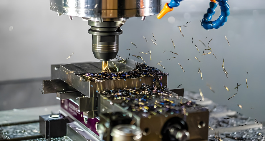
CNC machines such as milling machines (vertical and horizontal milling), routers, and lathes can operate at different axes to achieve the intended final product. Traditional 3-axis machines can sculpt the solid block along three linear axes (X, Y, and Z) to create relatively simpler parts. The 5-axis machining can manipulate the workpiece along three linear axes and around two rotational axes (A and B) to achieve more complex components.
CNC Machining Design Guidelines
There is no set of generally accepted standards in the CNC machining world, primarily due to the dynamic nature of the manufacturing industry and the machines used. Here are basic CNC machining design guides to ensuring excellence in your CNC machining operations:
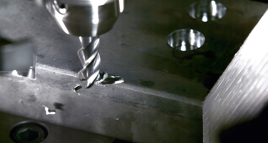
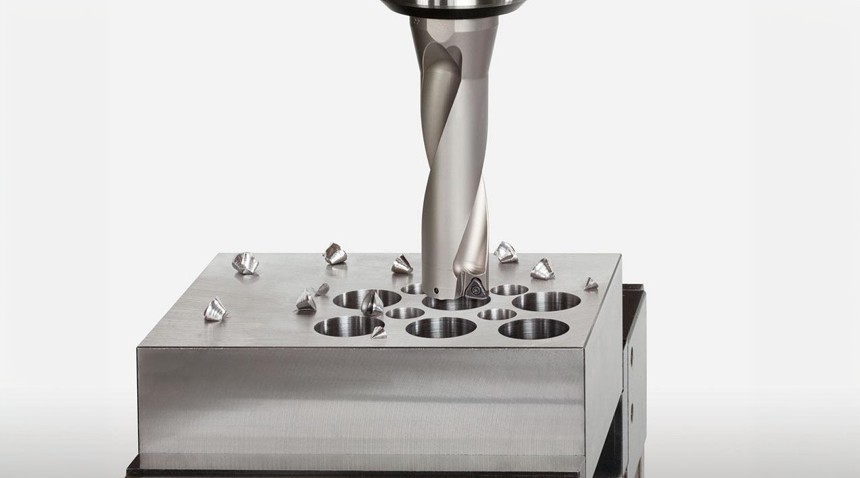
Holes
Machinists may use end mill tools or drill bits to make holes of desired depths and diameters. As a general recommendation when deciding the holes’ diameter in your design, Our experts advise using standard drill bit sizes measured in metric and imperial units.
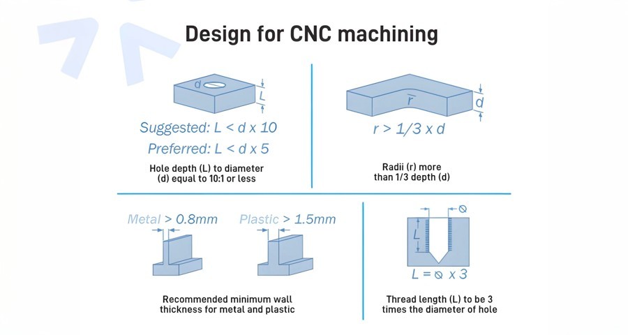
Any dimension above one millimeter is technically feasible. Machinists often use reamers and other boring tools to finish holes to ensure they are within a precise tolerance range. Thus, using a standard diameter for holes that demand great accuracy and are below 20 millimetres is advisable. Four times the nominal diameter is the recommended maximum depth for any hole when designing parts for CNC machining, but 40 times this value is achievable. Typically, the nominal diameter is 10 times the ratio.
You must use an end mill tool to machine holes with a non-standard diameter. The maximum cavity depth restrictions apply in this case, and you must use the recommended maximum depth value. Machinists drill holes deeper than the typical value with specialized drill bits with 3mm as the minimum diameter. Holes machined with end mills are flat, while blind holes made with a drill have a conical floor (135° angle). In CNC machining, there is no specific preference between blind holes or through holes.
Internal Edges
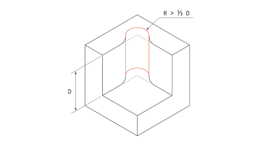
When machining inner edges, it is important to maintain at least one-third of the cavity depth. Adhering to the recommended internal corner radii allows you to use a suitable diameter tool and adhere to the recommended cavity depth guidelines.
Corner radii slightly greater than the recommended value permit the CNC tools to cut the internal edges along a circular path instead of a 90° angle, offering a superior finish with improved quality. Instead of lowering the corner radius, you can add a T-bone undercut in your CNC design if your part needs sharp 90° internal corners.
Threads
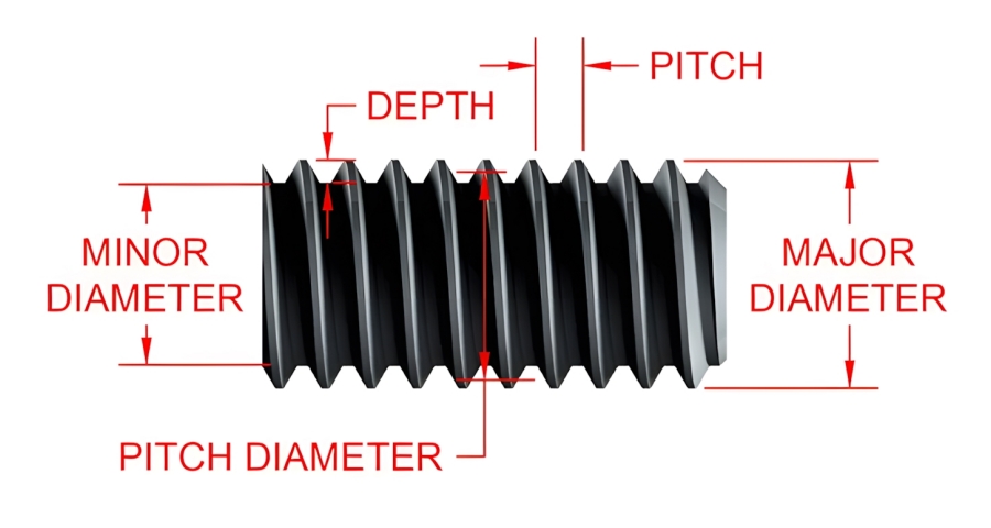
Threads are machined with taps, and external threads are cut with dies. M2 is the minimal thread size machinist used when CNC machining parts, but M6 or larger is typically ideal. However, machine operators can use CNC threading tools to cut threads down to M6 and mitigate the risk of tap breakage.
The advised minimum thread length is 1.5 times the nominal diameter, while the recommended length is three times the normal. Although cutting threads over 3 times the nominal diameter is unnecessary, add an unthreaded length at the hole’s bottom that is 1.5 times the nominal diameter when machining any thread smaller than M6.
Small or Raised Text
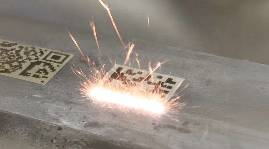
When CNC machining custom parts, you may need to define parts with serial numbers or company names. The recommended text and lettering are font size 20 or larger and 5 mm engraved. Many CNC machines possess pre-programmed routines for font texts.
Although time-consuming, adding text appears distinct in the custom CNC design. Experts recommend laser marking or electrochemical etching since they are better than embossed text and remove less material.
Cavities and Pockets
The industry-recommended cavity depth on any CNC design is 3 to 4 times its width because end mill tools have limited cutting lengths. Tool deflection, vibration, and greater chip evacuation might occur due to a lower depth-to-width ratio.
However, it would help to use a variable cavity depth and specialized tooling when your CNC design needs larger depths. Cavities with depths more than 6 times the tool diameter are deep. A tool diameter-to-cavity of about 30:1 is feasible with special tools.
Summarised in the table below:
CNC Machining Design Guidelines
| Design Element | Recommendations |
| Holes |
- Use standard drill bit sizes (metric and imperial). - Holes > 1mm feasible. - Use reamers for precise tolerances. - Standard diameter advised for holes < 20mm. - Max depth: 4x nominal diameter (up to 40x achievable). - For non-standard diameters, use end mill tools. - Blind holes have a conical floor (135° angle). |
| Internal Edges |
- Maintain at least one-third cavity depth. - Use recommended internal corner radii. - Corner radii > recommended value for circular cutting path. - Add T-bone undercut for sharp 90° internal corners. |
| Threads |
- Minimum thread size: M2 (ideal M6 or larger). - Minimum thread length: 1.5x nominal diameter. - Recommended thread length: 3x nominal diameter. - For threads < M6, add unthreaded length at hole bottom (1.5x nominal diameter). |
| Small or Raised Text |
- Recommended font size: 20 or larger. - Recommended engraving depth: 5 mm. - Use laser marking or electrochemical etching for better results and less material removal. |
| Cavities and Pockets |
- Recommended cavity depth: 3-4x width. - For larger depths, use variable depth and specialized tooling. - Deep cavities: >6x tool diameter. - Tool diameter-to-cavity ratio: up to 30:1 feasible with special tools. |
Basic Rules to Consider When Designing Parts for CNC Machining
Below are basic rules to keep in mind when making CNC designs:
- To avoid complications when making your CNC design, it would be best to consider the principal directions your CNC machine supports and its standard number of axes.
- Design CNC parts for seamless machining with large diameters using CNC cutting tools because it ensures rapid processing and prevents the need for specialty tools.
- Machining experts advise against using tool sizes less than 20 points when CNC machining texts on CNC parts to prevent mistakes within the engraved text.
- Avoid machining cavities more than four times deeper than their width because it complicates the CNC machining process.
Common CNC Design Restrictions
CNC designs typically have a few restrictions despite the robustness of the CNC technology and offer great flexibility. Below are design restrictions for CNC machining you need to understand to ensure smooth operations:
Tool Geometry
Most CNC cutters (drills and end mill tools) usually have a cylindrical shape and a restricted cutting length. The CNC cutting tool’s geometry is transferred to a workpiece as it removes material from the workpiece. Thus, the internal corners of a CNC part typically have a radius regardless of how small the cutting tool is.
Tool Access
Tool access is a major issue when a CNC machining workpiece has a considerable depth-to-width ratio since a CNC tool directly engages the workpiece from above to remove material. As such, features that are inaccessible from the top angle cannot be attained with CNC machining. However, this rule is inapplicable to machining undercuts in CNC parts.
For instance, machining the bottom of a deep cavity will require using tools with extended reach. This means a broader motion range for the end effector, which causes more machine chatter and reduces the achievable accuracy. Therefore, designing parts that are achievable with CNC machine tools with the largest diameter and short length is important to simplify production effectively.
One of the main approaches to mitigating tool access issues in machining CNC parts is to align the parts’ features, like vertical walls, holes, cavities, etc., to one of the six principal directions. Similarly, experts recommend using a 5-axis CNC machine with sophisticated workpiece holding capabilities because it helps resolve tool access restrictions.
CNC Machining Undercuts
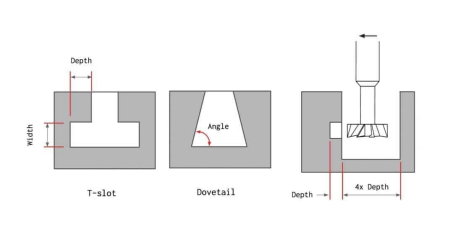
Undercuts are recesses in a CNC machined part’s corner, allowing better tool access and material removal during CNC machining. These features are unachievable with standard CNC tools because some of their surface are inaccessible from above. T-slots and dovetails are the two principal types of undercuts. These features can be one-sided or double-sided and are cut into CNC parts using special tools.
Machinists use T-slot tools of horizontal cutting blades attached to a vertical shaft to machine undercuts. An undercut’s width can vary between 3 millimeters and 40 millimeters. On the other hand, the angle is the defining feature size for dovetail cutting tools. 45° and 60° dovetail tools are standard tools for making dovetail undercuts. Although CNC tools with an angle of 5-, 10, and about 120° already exist, machinists hardly use them.
Below are best practices for designing undercuts for CNC machining:
- Add enough clearance for the cutter when designing CNC parts undercuts on internal walls. A general rule is to add space equal to at least four times the undercut’s depth between the machined wall and any other internal wall.
- The ratio between the cutting diameter and the shaft’s diameter is 2:1 for standard CNC tools, restricting the cutting depth. However, it is a common practice for CNC machine shops to fabricate their custom undercut tools when a non-standard undercut is required. Nonetheless, it is important to avoid it if possible since this can increase machining time and cost.
Expert Practices in Designing Parts with CNC Machining
Adhering to expert practices and CNC machining basics will help achieve high-quality and precise machined products when designing parts with CNC machining. Depending on the machining type, here are expert practices to be maintained when designing CNC machining:
Design for CNC Drilling
CNC drilling is a subtractive manufacturing process that product designers use to create holes in workpieces. CNC tools used in this process have a conical tip, enabling them to dig deeply into the raw material during machining. When fabricating a design intended for CNC drilling, below are helpful suggestions to consider:
Avoid Partial Holes
Machining experts recommend that it is best to avoid partial holes when CNC machining parts because there is a high possibility the tip will wander. However, if partial holes are unavoidable, you can keep the drill axis on the material so that the workpiece holds most of the hole.
Avoid Drilling through Cavities
When determining the hole locations in your CNC design ideas, ensure they don’t intersect with already existing cavities in the CNC part. However, if it is inevitable, the drilled hole can slightly intersect with the cavity when its central axis doesn’t intersect with the cavity.
Appropriate Hole Depth
Drilling holes that are too deep in CNC parts causes complications. Thus, it would be best to avoid drilling deeper than 12 times the closest bit diameter to achieve the appropriate hole depth. Drill bits with this length or longer cannot maintain a tight tolerance and have a high chances of breaking. Similarly, you should consider a larger hole diameter if you need to dig deeper.
Nevertheless, drilling from both sides of the CNC part is a reliable alternative if a deep hole is necessary. However, the manufacturing process may be costly and take longer since it will require a second machining setup.
Keep the Drill Axis Perpendicular to the Surface
When drilling a hole in CNC parts, keeping the drill axis perpendicular to the workpiece surface is paramount to avoid tip wander. Making a shallow, flat-bottomed pocket on a round/cylindrical object’s surface often allows the drill to cut the part’s surface perpendicularly.
Moreover, experts advise machining a pilot hole to resolve this challenge, even though it is compulsory during CNC machine programming rather than when designing CNC parts.
Design for CNC Turning
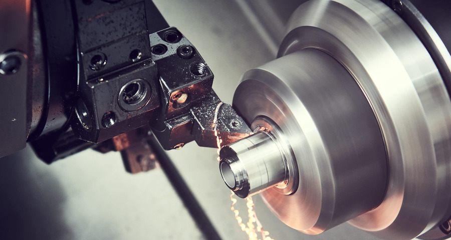
This machining process creates parts with axial symmetry and cylindrical geometry on CNC lathes. In the CNC turning process, the cutting tools engage the rotary workpiece held on a chuck to cut it into preferred shapes. CNC-turned parts possess a superior surface finish and tighter tolerance. Below are helpful tips for making successful designs for CNC operations using a turning machine:
Avoid Thin Walls
Excessive material removal can result in unnecessary stress on the machined component. Besides, walls that are too thin reduce rigidity and can make it difficult to achieve tight tolerances. Hence, experts recommend 0.02 inches as the minimum wall thickness of the turned section in your design process for CNC machining.
Avoid Long, Thin Parts
When CNC turning parts, don’t use long, thin-turned parts due to the high possibility of spinning unevenly and chattering against the CNC tool. Leave room for a center drill on the free end and keep the workpiece spinning straight with a center when making a lengthy component. Also, it is a general guideline to maintain a length-to-diameter of 8:1 or less.
Avoid Sharp Internal and External Corners
It is important to avoid sharp corners (inside and outside) when designing parts for CNC machining. Experts recommend adding a radius to the internal corner of your parts’ design to prevent the CNC tool from running up a larger surface. You can also avoid shard corners by slightly slanting a steep sidewall. However, machining contours with a single lathe cutting tool is simpler since it requires fewer processes.
Feature Symmetry
Generally, every machined feature on a CNC-turned part must be symmetrical around the turning axis. Adding non-axially symmetric features and geometry will require more complex machining and setups. Typical excellent CNC turning features include steps, chamfers, tapers, and curves.
Adding features to a non-axially symmetric CNC-turned part is sometimes necessary, which may require a different operation. Hence, you can maintain a bit of symmetry when it is not necessary.
Design for CNC Milling
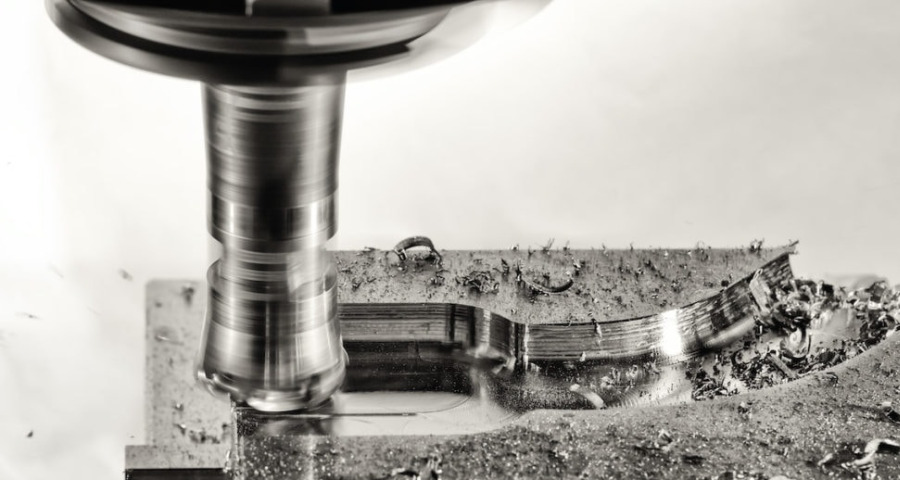
CNC milling is a machining technique involving the rapid removal of material from a solid block using round CNC tools to achieve the preferred shape and feature. The milling machines are available in varying designs ranging from 3-axis to 12-axis. Here are best practices for designing for CNC milling operations:
Examine Available CNC Tools
While drafting design ideas for your CNC parts, it is paramount to examine the various cutting tools typically accessible for CNC milling operations. Machining time and costs will be significantly reduced, provided the required features and complex geometry are achievable using standard tools. More so, a design with a radius smaller than the standard radius would cause design complications and increase cost. Hence, consider tool standard sizes when drafting your design for CNC turning.
Design with the Largest Possible Internal Radii
Bigger CNC cutters shear more material per minute, reducing CNC machining costs and time. Thus, expert machinists recommend using maximum allowable internal radii when designing and avoiding radii smaller than 0.8mm when feasible.
Likewise, ensure the filets are slightly larger than the radius of the end mills. For instance, use a radius of 3.3mm (0.130 inches) instead of 3.175mm (0.012 inches). Hence, it offers a finer polish since the mill follows a smoother route.
Avoid Deep Narrow Slots
Poor surface finish often occurs in CNC milling due to constant deflection and vibration of lengthy tools. Thus, the final depth of cut of an end mill should not exceed 5 times its diameter for cutting steel, 10 times its diameter for cutting aluminum, and 15 times its diameter for cutting plastic.
For example, a slot cut in a 55-inch steel part wide with a 0.5-inch end mill with 0.55 inches width should not exceed a depth of 2.75 inches. If possible, reach the feature from two directions to reduce the length of the tool required.
Avoid Sharp Internal Corners
Since the cutting tools used in CNC milling are generally round, it is impossible to create sharp corners using CNC mills. To utilize a CNC mill to cut internal corners, the part’s corners must have radii larger than the milling cutting tools used. Usually, the cutting tool diameter needs to be twice the radius of the corner it cuts. For example, you need a ¼ inch cutter when making fillets larger than 1/8 inch.
Filets are also required when a drafted or sloped surface meets vertical walls or sharp edges. However, a square or ball end mill often leaves material between the cutting surface below and the wall unless the surface remains flat and normal to the cutter.
AT-Machining: The Reliable Machine Shop for Your CNC Machining Design Parts
Designing parts for CNC machining requires top-notch CNC machining skills since it involves considering specific guidelines to ensure accurate, efficient, and cost-effective parts fabrication. Understanding and adhering to these principles when making CNC designs is critical to achieving excellent machining outcomes.
AT-Machining is an ideal CNC shop to partner with for professional assistance with your design for CNC machining. Our experienced and certified engineers can leverage our modern digital design technologies to elevate your products to the next level. We can offer professional assistance with design and prototyping for various manufacturing processes, from 3D printing, urethane casting, injection molding, and other CNC machining operations. You can upload your CAD models on our fast and reliable quoting platform for an instant quote. Contact us now to discuss your CNC parts design with our professionals!