Skip to content
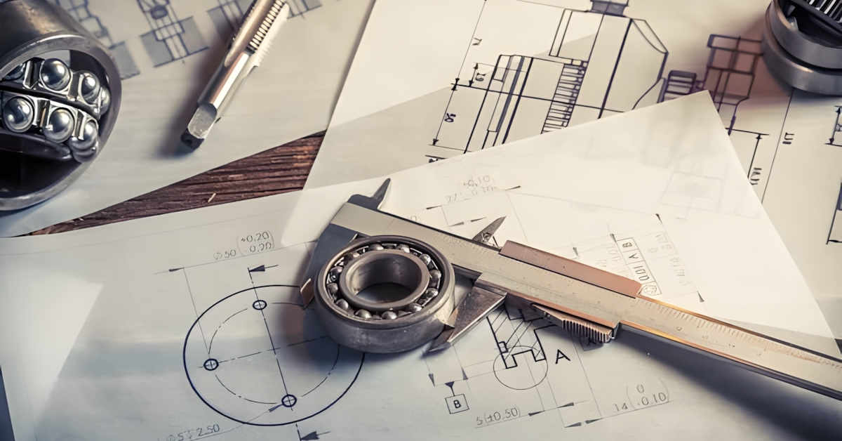
What Does Tolerance Mean in Engineering?
Tolerance is an engineering concept that measures the unplanned variation in a machined part’s nominal dimension or measured value. It is a numeric value with a plus or minus sign and cannot be zero (0). Generally, even the most precise CNC machine cannot always create a part with dimensions that match the design specifications. Since there is often some degree of variation due to varying raw material properties and inherent machine inaccuracies, it is crucial to understand engineering tolerances and types to produce quality and usable machined parts.
The primary objective of engineering experts and machinists is to leverage their skills and experience to bring these deviations within an acceptable range of lower and upper limits. This range is determined by tolerance, which establishes an upper and lower limit on how much the dimension can vary from its true value. Tolerance specifies the maximum and minimum limits of linear, angular, and other physical dimensions on a technical drawing.
Types of Engineering Tolerances
Engineers and product designers use various engineering tolerances to specify the fundamental deviation in a component’s basic dimensions since they offer accurate insight into the intended functionality and manufacturing requirements. Below are the types of tolerances in engineering:
Dimension Tolerances
Dimension tolerance refers to the acceptable variation in the dimension or size. This basic engineering tolerance comprises a maximum and minimum limit. The maximum dimension refers to the maximum allowable sizes/limits, while the minimum dimension refers to the minimum permissible sizes.
Upper or lower deviation may occur when specifying dimension tolerances. The upper deviation shows the allowable maximum variation your mechanical components can have relative to the nominal value. A “+” sign often precedes it. Lower deviation indicates the minimum allowable variation in your part’s measurement preceded by a “-” sign.
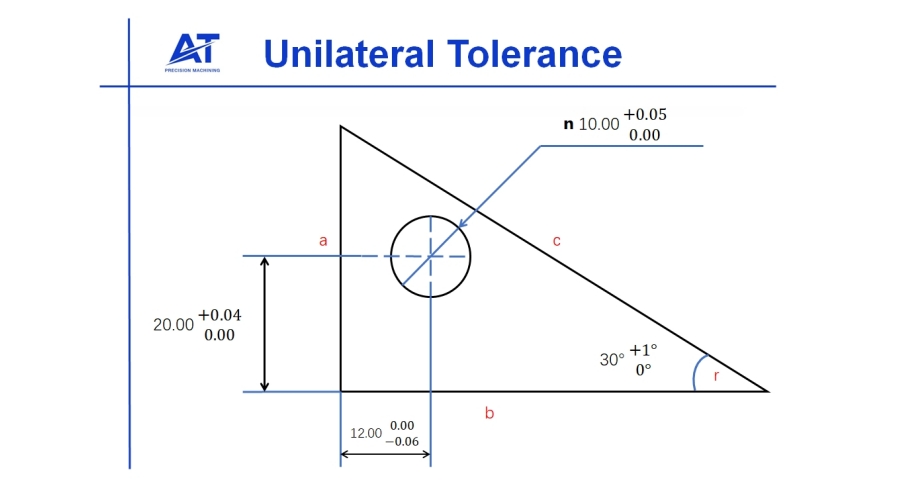
Unilateral tolerances refer to when two limit dimensions are in the same or only one direction (either below or above the tolerances). However, there may be a case where the limits coincide with the actual size.
Conversely, bilateral tolerance specifies the preferred tolerance zone on both sides of the nominal value. Hence, bilateral tolerances permit variation in both negative and positive directions. Moreover, bilateral tolerance varies and works best when deviation is not specified in any particular direction. For more information on dimensional tolerances, please visit our blog “Engineering Tolerances: Definition, Types, and Fits“.
General Tolerances
Apart from tolerances for specific dimensions and characteristics, those unspecified dimensions are often required to adhere to particular standards in engineering drawings. General tolerances can be included in a drawing as a note or table. They often apply to conditions like linear dimensions, chamfer height, angular dimension, external radius, etc. ISO 2768 is a typical international tolerance standard used in Europe.
Geometric Dimensioning and Tolerancing (GD&T)
| Symbol | Characteristics | Categories |
|---|---|---|
 | Straightness | Form |
 | Flatness | |
 | Circularity | |
 | Cylindricity | |
 | Angularity | Orientation |
 | Perpendicularity | |
 | Parallelism | |
 | Position | Location |
 | Circular Runout | Runout |
 | Total runout | |
 | Profile of a line | Profile |
 | Profile of a surface |
GD&T is an advanced and more complex system that introduces another aspect of mechanical tolerance basics. It is a universally acceptable way of specifying the geometric tolerances for engineering parts using in-part references. It identifies the precise geometric characteristic of the area where the machining tolerances apply. Geometric dimensioning and tolerancing apply to part characteristics such as true position, flatness, and concentricity.
Why Is Tolerance Important in Manufacturing?
Tolerance is universal and realistic in machining because it sets a reference range of dimensional deviations that machinists can use as a scope or target. For instance, a machining expert may use a regular machine instead of a precision CNC machine with +/- 0.001 mm accuracy to fabricate parts with only +/-1 mm tolerance requirements. This would effectively save machining costs, time, and resources.
Moreover, tolerance grades offer a guideline to the quality department on how to effectively confirm a part’s dimensions after machining. Engineers often use advanced tolerancing techniques such as tolerance stacking to communicate design intent.
Tolerance remains a necessary provision for interchangeable components. Each machined part must be similar to a specific tolerance level in CNC machine shops with bulk orders. The tolerance values provide the base standard for a part to be the same as the rest of its batch.
Standard Tolerancing Strategies in Engineering Drawings
In this section, we will explore the different tolerancing strategies in technical drawings and their:
Direct Limits
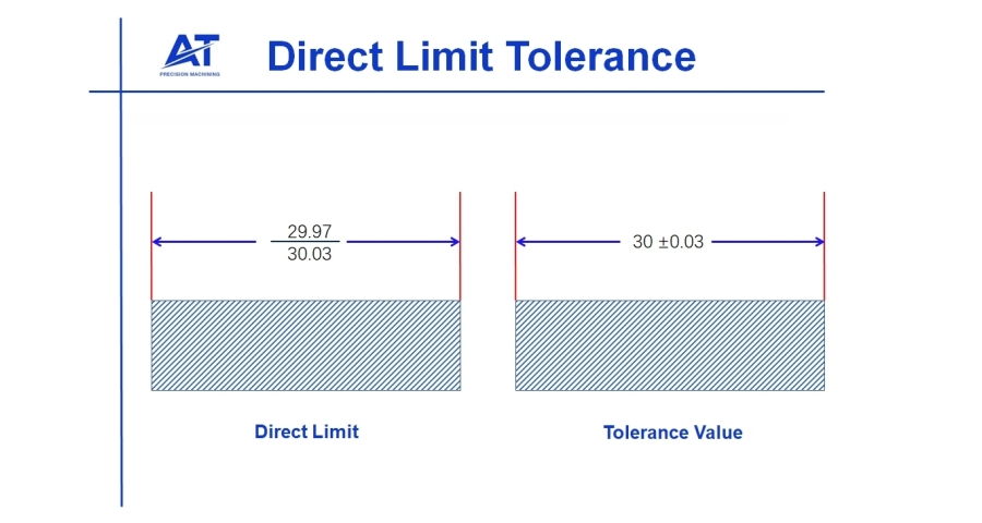
Direct limit tolerancing specifies only the minimum and maximum permissible size of a dimension. It is one of the commonly used tolerancing techniques in engineering drawings. Engineers and machinists often use this method because of its clarity and space-saving benefits. However, the dimension’s base value remains unknown and can be annoying if you need it. The illustration below shows that dimensions can vary between 29.97 and 30.03 through direct limit tolerances.
Plus and Minus Tolerances
Plus and minus tolerances are popular and alternative tolerancing methods in engineering drawings. These tolerances indicate tolerance as a positive and negative deviation (±) from the basic size. Even though it takes more space than direct limits and can make an engineering drawing look clumsy, it is often straightforward and informative.
Tolerances can be unilateral or bilateral within this system. A unilateral tolerance illustrates a variation on a specific side of the basic size and can be positive or negative. Bilateral tolerances define variation on both sides of the basic size and have positive and negative deviations. For more detailed information on unilateral and bilateral tolerances, you can visit our blog “Understanding Unilateral Tolerance and Bilateral Tolerance in Machining”
What Does Allowance Mean in Engineering?
Allowance refers to the intentional difference or deviation of the mating part’s specific dimension to create the correct mate or achieve press fitting. This essential design requirement enables functional engineering to fit in mechanical assemblies. The shaft and hub assembly is an apt example that best explains allowance in engineering.
The designer of both components defines the maximum shaft size and minimum hole size to achieve an engineering fit. A positive allowance indicates that a small gap is present between the mating surfaces, while a negative allowance shows that there is an interference between both parts.
Allowance and Engineering Fits
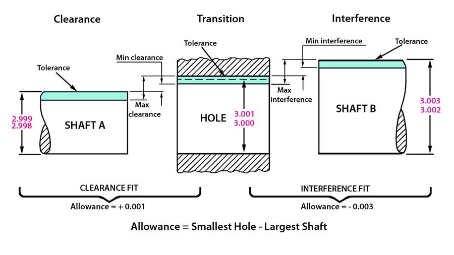
Engineering fits are integral to mechanical engineering because they combine mating parts’ tolerance and allowance. The required type of engineering fit determines allowance in engineering. There are three main types of fits for hub-shaft systems. These include clearance fit, transition fit, and interference fit.
The above illustration shows that, mathematically, allowance refers to the difference between the largest shaft diameter and the smallest hole. For the clearance fit illustration, the shaft size cannot exceed 2.999, while the hole size cannot be less than 3.000. Besides, the minimum interference and maximum interference fit ensure the mating parts fit together perfectly without being too tight or loose.
However, note that both the shaft and hub possess their tolerances, as represented in green. These tolerance ranges are specified on both components and work together to achieve the correct allowance between mating parts after assembly.
Types of Engineering Fits
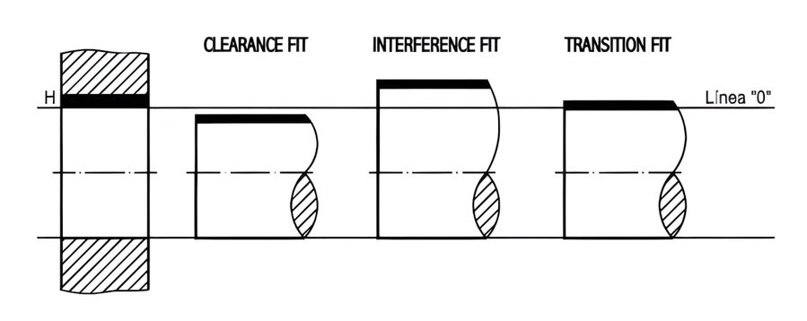
Engineering fits are of three main types, including:
Clearance Fits
Clearance fits have a positive allowance specifying that there is a gap or clearance between two mating parts. These fits suit mating parts requiring ease of motion or relative assembly. This type of fit works well with parts such as shafts and fasteners where a particular amount of movement is permissible.
Transition Fits
A transition fit combines both clearance and interference fits because they have positive and negative allowances. Transition fits enable the combination of clearance and interference within specific limits. They offer flexibility in assembly and maintain a certain level of interference for stability.
Interference Fits
These fits have a negative allowance, showing that the mating parts are purposely designed to interfere or overlap. The components of an assembly in such fits are often pressed or forced together to create a tight and secure connection. These fits are widely used in applications requiring rigid, non-slip connections like press-fitted bearings.
Why Is Allowance Important in Production?
Design engineers assign individual part tolerances according to practical manufacturing constraints. As a result, machinists are more meticulous and pay more attention and resources to machined parts with accurate engineering fits because it provides precise allowance and tolerance range.
Thus, allowance and tolerance work together in mechanical assemblies, and this reality leads to confusion. As stated earlier, allowance is a design feature indicating the planned deviation in mating components’ dimensions. Moreover, the engineering fit will not function as intended if both parts of an assembly are not machined precisely to the defined allowance..
Benefits of Including Tolerance and Allowance in Parts’ Design
Despite the difference between tolerances and allowance in manufacturing processes, they collectively offer vast benefits in designing and manufacturing efficient and reliable mechanical parts. Below are the expected benefits of including tolerance and allowance in engineering:
- Tolerance and allowance facilitate the interchangeability of mating parts from different suppliers or batches, ensuring they fit perfectly without custom fitting.
- These key concepts help reduce machining costs by reducing the need for precision machining, which can be expensive.
- Engineering tolerances and allowances simplify the assembly process, ensure machined parts function properly, and meet the required design specifications, preventing the need to rework or readjust manufactured parts.
- Tolerance and allowance encourage innovation and design flexibility by providing a framework for design testing and optimization. Product designers and engineers can prototype parts with varying tolerances to determine the optimal balance between manufacturability and performance.
- Practical tolerances and allowances facilitate the efficient use of manufacturing technologies and techniques while ensuring quality control.
- Since deviation from a specified tolerance range can attract legal consequences, tolerances and allowances in engineering help ensure various industries meet the stringent regulations and quality standards.
Differences between Tolerance and Allowance
The chart below summarizes the prescribed difference between tolerances and allowance in engineering.
| Aspect | Tolerance | Allowance |
|---|---|---|
| Definition | Tolerance means the permissible deviation from a defined dimension or feature of a mechanical part. | It is the intentional gap between components of an assembly. |
| Purpose | Tolerance ranges help control quality by defining the acceptable variation range while accommodating manufacturing variability. | Allowance ensures mating parts fit correctly, considering variables such as thermal expansion, manufacturing variations, lubrication, etc. |
| Types | Upper limit (positive value) and lower limit (negative value). | Clearance (positive value) or interference (negative value). |
| Material and Lubrication Impact | Material and lubrication may influence the need for looser or tighter tolerances. | Material and lubrication may affect the ideal allowance values. |
| Adjustability | Engineering tolerances do not permit variability in part dimensions but allow for manufacturing variations. | Allowance in engineering permits varying levels of gap or overlap between mechanical parts to create the desired fit. |
| Function in Assembly | Defines the acceptable range of dimensions for features, parts, and assemblies. | It dictates the type of fit between mating parts. |
| Typical Application | Product engineers use tolerances to control the acceptable range of a mechanical part’s lengths, diameter, or other dimensions. | It is suitable for indicating how freely mating parts should move (clearance) or how they should be press-fitted (interference). |
Conclusion
Tolerance and allowance are easily mixed up since they represent similar themes in engineering design; although linked, they are different. As design engineers and machining experts, it is crucial to understand their distinctions to make accurate and practical designs that facilitate easy interchangeability of parts and components. Tolerances limit machining inaccuracy, while allowance helps achieve a specific engineering fit by providing a reference against which to work.
AT-Machining is the ideal partner for rapid manufacturing and prototyping services. Our professionals leverage our advanced CNC facility and good years of experience to meet high-quality production and stringent industry standards. AT-Machining is the right industrial expert to contact whenever you need professional assistance determining the suitable allowance for your engineering fit or tight tolerances for critical components. Contact AT Machining now if you have any inquiries about tolerances and allowances in engineering!